Table of Contents
Advertisement
Advertisement
Table of Contents

Subscribe to Our Youtube Channel
Related Manuals for MSI MS-7275


Summary of Contents for MSI MS-7275
- Page 1 MS-7275 MS-7275 (V1.2) Mainboard...
-
Page 2: Table Of Contents
CONTENTS Chapter 1 Getting Start ..................1-1 Mainboard Specifications .................. 1-2 Mainboard Layout ....................1-4 Packing Checklist ....................1-4 Chapter 2 Hardware Setup .................. 2-1 Quick Components Guide ................... 2-2 CPU (Central Processing Unit) ................2-2 Introduction to LGA 775 CPU ..............2-3 CPU &... - Page 3 Chapter 3 BIOS Setup .................... 3-1 Entering Setup ....................3-2 Control Keys ....................3-3 The Main Menu ....................3-4 Standard CMOS Features .................. 3-6 Advanced BIOS Features .................. 3-8 Integrated Peripherals ..................3-10 Advanced Chipset Features ................3-11 Power Management Setup ................3-12 PNP/PCI Configurations ..................
- Page 4 Getting Started Chapter 1 Getting Started Thank you for choosing the RC410 + SB600 Series (MS-7275 v1.2) Micro ATX mainboard. The RC410 + ® SB600 Series mainboards are based on ATI RC410 & SB600 chipsets for optimal system efficiency. Designed ®...
-
Page 5: Mainboard Specifications
MS-7275 Mainboard Mainboard Specifications Processor Support* - Intel ® Pentium D 9xx "Presler"Dual Core processor, 800 MHz Systembus, 65 nm, Only 95W ® - Intel Pentium D 8xx "Smithfield" Dual Core processor, 800 MHz Systembus, Only 95W ® - Intel P4 HT 6xx "Cedar Mill", 800/533 MHz Systembus, 65 nm... - Page 6 Getting Started Connectors Backpannel - 1 serial port (COM1) - 1 D-Sub VGA port. - 1 Optical SPDIF jack. - 1 IEEE 1394 port - 4 USB 2.0 Ports. - 1 LAN jack - 6 flexible audio jacks. On-Board Pinheaders - 1 front Audio pinheader - 1 SPDIF out pinheader - 1 AUX in pinheader...
-
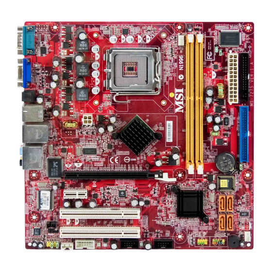
Page 7: Mainboard Layout
Top: 1394 port Bottom: USB ports JPW1 Top: LAN Jack Bottom: USB ports Line-In Line-Out T:RS-Out BATT M:CS-Out PCIE16X1 RTL8100C B:SS-Out BIOS PCIE1X1 VT6307 PCI1 SPDOUT1 PCI 2 ALC888 JUSB2 JUSB1 JAUX1 JFP2 JFP1 JAUD1 J1394_1 MS-7275 v1.2 Micro-ATX Mainboard... -
Page 8: Chapter 2 Hardware Setup
Hardware Setup Chapter 2 Hardware Setup This chapter provides you with the information about hardware setup procedures. While doing the installa- tion, be careful in holding the components and follow the installation procedures. For some components, if you install in the wrong orientation, the components will not work properly. -
Page 9: Quick Components Guide
MS-7275 Mainboard Quick Components Guide CPU_FAN1 p,2-13 DDR DIMMs p,2-3 JPW1 p,2-7 p,2-8 JBR1 p,2-3 JPWD1 p,2-15 ATX1 p,2-8 FDD1 p,2-11 Back Panel I/O p,2-9 IDE1 p,2-11 JCMOS1 PCI-E Slots p,2-3 p,2-3 JWP1 p,2-14 SATA1~4 p,2-12 SPDOUT1 SYS_FAN1 p,2-15 p,2-13... -
Page 10: Cpu (Central Processing Unit)
When you are installing the CPU, make sure to install the cooler to prevent overheating. If you do not have the CPU cooler, contact your dealer to purchase and install them before turning on the computer. For the latest information about CPU, please visit http://www.msi.com.tw/program/ products/mainboard/mbd/pro_mbd_cpu_support.php. Important 1. -
Page 11: Cpu & Cooler Installation
MS-7275 Mainboard CPU & Cooler Installation When you are installing the CPU, make sure the CPU has a cooler at- tached on the top to prevent overheating. If you do not have the cooler, contact your dealer to purchase and install them before turning on the computer. Meanwhile, do not forget to apply some silicon heat transfer compound on CPU before installing the heat sink/cooler fan for better heat dispersion. - Page 12 Hardware Setup Important 1. Confirm if your CPU cooler is firmly installed before turning on your sys- tem. 2. Do not touch the CPU socket pins to avoid damaging. 3. The availability of the CPU land side cover depends on your CPU packing. 5.
- Page 13 MS-7275 Mainboard 9. Press down the load lever lightly 10. Align the holes on the mainboard onto the load plate, and then se- with the heatsink. Push down the cure the lever with the hook under cooler until its four clips get retention tab.
-
Page 14: Memory
Hardware Setup Memory The mainboard provides two 240-pin non-ECC DDRII DIMMs. For more information on compatible components, please visit http://www.msi.com.tw/ program/products/mainboard/mbd/pro_mbd_trp_list.php. DDRII 240-pin, 1.8V 64x2=128 pin 56x2=112 pin Installing DDRII Modules 1. The memory module has only one notch on the center and will only fit in the right orientation. -
Page 15: Atx 24-Pin Power Connector: Atx1
MS-7275 Mainboard Power Supply ATX 24-Pin Power Connector: ATX1 This connector allows you to connect an ATX 24-pin power supply. To connect the ATX 24-pin power supply, make sure the plug of the pin 13 power supply is inserted in the proper orientation and the pins are aligned. -
Page 16: Back Panel
Hardware Setup Back Panel L-In RS-Out 1394 Port L-Out CS-Out VGA Port Serial Port SS-Out USB Ports SPDIF Out Serial Port Connector The serial port is a 16550A high speed communications port that sends/ receives 16 bytes FIFOs. You can attach a serial mouse or other serial devices directly to the connector. - Page 17 MS-7275 Mainboard Audio Port Connectors These audio connectors are used for audio devices. You can differentiate the color of the audio jacks for different audio sound effects. Blue audio jack - Line In Green audio jack - Line Out, is a connector for speakers or headphones.
-
Page 18: Connectors
Hardware Setup Connectors Floppy Disk Drive Connector: FDD1 This standard FDD connector supports 360K, 720K, 1.2M, 1.44M and 2.88M floppy disk types. FDD1 Hard Disk Connector: IDE1 The mainboard provides a one-channel Ultra ATA 100 bus Master IDE controller that supports PIO mode 0~4, Bus Master, and Ultra DMA 33/66/100 function. -
Page 19: Serial Ataii Connectors: Sata1~Sata4
MS-7275 Mainboard Serial ATAII Connectors: SATA1~SATA4 SATA1~SATA4 are high-speed Serial ATA interface ports. Each supports 2 genera- tion serial ATA data rates of 300MB/s and is fully compliant with Serial ATA 2.0 specifications. Each Serial ATA connector can connect to 1 hard disk device. -
Page 20: Ieee 1394 Connectors: J1394_1
Hardware Setup Fan Power Connectors: CPU_FAN1, SYS_FAN1 The fan power connectors support system cooling fan with +12V. When connecting the wire to the connectors, always take note that the red wire is the positive and should be connected to the +12V, the black wire is Ground and should be connected to GND. -
Page 21: Bios Password Clear: Jpwd1
MS-7275 Mainboard BIOS Password Clear: JPWD1 JPWD1 The BIOS password protects the BIOS from undesired changes. If you need to clear the BIOS password, use the following steps: 1. Turn off the PC and unplug the power cord. 2. Remove the JPWD1 jumper cap. -
Page 22: Front Panel Connectors: Jfp1/Jfp2
Hardware Setup Front Panel Connectors: JFP1/JFP2 The mainboard provides two front panel connectors for electrical connection to the front panel switches and LEDs. The JFP1 is compliant with Intel ® Front Panel I/O Connectivity Design Guide. Power Power Speaker Switch JFP2 JFP1 Power... -
Page 23: Front Panel Audio Connector: Jaud1
MS-7275 Mainboard Front Panel Audio Connector: JAUD1 The JAUD1 front panel audio connector allows you to connect the front panel audio and is compliant with Intel ® Front Panel I/O Connectivity Design Guide. JAUD1 JAUD1 Pin Definition SIGNAL DESCRIPTION AUD_MIC... -
Page 24: Front Usb Connectors: Jusb1, Jusb2
Hardware Setup Front USB Connectors: JUSB1, JUSB2 The mainboard provides two USB 2.0 pinheaders (optional USB 2.0 bracket avail- able) that are compliant with Intel ® I/O Connectivity Design Guide. USB 2.0 technology increases data transfer rate up to a maximum throughput of 480Mbps, which is 40 times faster than USB 1.1, and is ideal for connecting high-speed USB interface peripherals such as USB HDD, digital cameras, MP3 players, printers, mo- dems and the like. -
Page 25: Clear Cmos Jumper: Jcmos1
MS-7275 Mainboard Jumpers Clear CMOS Jumper: JCMOS1 There is a CMOS RAM onboard that has a power supply from external battery to keep the data of system configuration. With the CMOS RAM, the system can automatically boot OS every time it is turned on. If you want to clear the system configuration, set the JCMOS1 (Clear CMOS Jumper ) to clear data. -
Page 26: Pci (Peripheral Component Interconnect) Express Slots
Hardware Setup Slots PCI (Peripheral Component Interconnect) Express Slots PCI Express architecture provides a high performance I/O infrastructure for Desktop Platforms with transfer rates starting at 2.5 Giga transfers per second over a PCI Express x1 lane for Gigabit Ethernet, TV Tuners, 1394 controllers, and general pur- pose I/O. -
Page 27: Pci Interrupt Request Routing
MS-7275 Mainboard PCI Interrupt Request Routing The IRQ, acronym of interrupt request line and pronounced I-R-Q, are hardware lines over which devices can send interrupt signals to the microprocessor. The PCI IRQ pins are typically connected to the PCI bus pins as follows:... -
Page 28: Chapter 3 Bios Setup
BIOS Setup Chapter 3 BIOS Setup This chapter provides information on the BIOS Setup program and allows you to configure the system for optimum use. You may need to run the Setup program when: An error message appears on the screen during the system booting up, and requests you to run SETUP. -
Page 29: Entering Setup
MS-7275 Mainboard Entering Setup Power on the computer and the system will start POST (Power On Self Test) pro- cess. When the message below appears on the screen, press <DEL> key to enter Setup. Press DEL to enter SETUP If the message disappears before you respond and you still wish to enter Setup, restart the system by turning it OFF and On or pressing the RESET button. -
Page 30: Control Keys
BIOS Setup Control Keys <↑> Move to the previous item <↓> Move to the next item <←> Move to the item in the left hand <→> Move to the item in the right hand Select the item <Enter> Jumps to the Exit menu or returns to the main menu from a <Esc>... -
Page 31: The Main Menu
MS-7275 Mainboard The Main Menu Standard CMOS Features Use this menu for basic system configurations, such as time, date etc. Advanced BIOS Features Use this menu to setup the items of AWARD ® special enhanced features. Advanced Chipset Features Use this menu to change the values in the chipset registers and optimize your system’s performance. - Page 32 BIOS Setup BIOS Setting Password Use this menu to set the password for BIOS. Save & Exit Setup Save changes to CMOS and exit setup. Exit Without Saving Abandon all changes and exit setup.
-
Page 33: Standard Cmos Features
MS-7275 Mainboard Standard CMOS Features The items in Standard CMOS Features Menu includes some basic setup items. Use the arrow keys to highlight the item and then use the <+> or <-> keys to select the value you want in each item. - Page 34 BIOS Setup Halt On The setting determines whether the system will stop if an error is detected at boot. Available options are: [No Errors] The system doesn’t stop for any detected error. [All, But Keyboard] The system doesn’t stop for a keyboard error. **System Information** CPU Type and memory status of your system (read only).
-
Page 35: Advanced Bios Features
MS-7275 Mainboard Advanced BIOS Features Quick Boot Setting the item to [Enabled] allows the system to boot within 5 seconds since it will skip some check items. Boot Sector Protection This function protects the BIOS from accidental corruption by unauthorized users or computer viruses. - Page 36 BIOS Setup Full Screen LOGO Display This item enables you to show the company logo on the bootup screen. Settings are: [Enabled] Shows a still image (logo) on the full screen at boot. [Disabled] Shows the POST messages at boot. Boot Sequence Press <Enter>...
-
Page 37: Advanced Chipset Features
MS-7275 Mainboard Advanced Chipset Features Important Change these settings only if you are familiar with the chipset. Memory Bank Alignment The field specifies the value of memory banks. UMA Frame Buffer Size Frame Buffer is the video memory that stores data for video display (frame). This field is used to determine the memory size for Frame Buffer. - Page 38 BIOS Setup Integrated Peripherals USB Controllers Select [Enabled] if your system contains a Universal Serial Bus (USB) controller and you have USB peripherals. USB Device Legacy Support Select [Enabled] if you need to use a USB-interfaced device in the operating system. Onboard LAN Controller This setting allows you to enable/disable the onboard LAN controller.
- Page 39 MS-7275 Mainboard I/O Devices Configuration Press <Enter> to enter the sub-menu: COM Port 1 This item allows you to select Serial Port1 base addresses. SATA Devices Configuration Press <Enter> to enter the sub-menu: OnChip SATA Channel This allows you to enable or disable onchip Serial ATA controller.
-
Page 40: Power Management Setup
BIOS Setup Power Management Setup Important S3-related functions described in this section are available only when your BIOS supports S3 sleep mode. ACPI Function This item is to activate the ACPI (Advanced Configuration and Power Management Interface) Function. If your operating system is ACPI-aware, such as Windows 98SE/ 2000/ME/XP, select [Enabled]. - Page 41 MS-7275 Mainboard Re-Call VGA BIOS from S3 Selecting [Enabled] allows BIOS to call VGA BIOS to initialize the VGA card when system wakes up (resumes) from S3 sleep state. The system resume time is short- ened when you disable the function, but system will need an AGP driver to initialize the VGA card.
-
Page 42: Pnp/Pci Configurations
BIOS Setup PNP/PCI Configurations This section describes configuring the PCI bus system and PnP (Plug & Play) feature. PCI, or Peripheral Component Interconnect, is a system which allows I/O devices to operate at speeds nearing the speed the CPU itself uses when communicating with its special components. -
Page 43: H/W Monitor
MS-7275 Mainboard H/W Monitor This section shows the status of your CPU, fan, overall system status, etc. Monitor function is available only if there is hardware monitoring mechanism onboard. Spread Spectrum When the motherboard’s clock generator pulses, the extreme values (spikes) of the pulses creates EMI (Electromagnetic Interference). - Page 44 BIOS Setup Smart Fan Tolerance You can select a fan tolerance value here for the specific range for the “Smart CPU Fan” item. If the current temperature of the fan reaches to the maximum threshold (the temperatures set in the “Smart CPU Fan” plus the tolerance values you set here), the fan will speed up for cooling down.
-
Page 45: Load Optimized Defaults
MS-7275 Mainboard Load Optimized Defaults The Optimized Defaults are the default values set by the mainboard manufacturer specifically for optimal performance of the mainboard. When you select Load Optimized Defaults, a message as below appears: Pressing Y loads the default factory settings for optimal system performance. -
Page 46: Bios Setting Password
BIOS Setup BIOS Setting Password When you select this function, a message as below will appear on the screen: Type the password, up to 6 characters in length, and press <Enter>. The password typed now will replace any previously set password from CMOS memory. You will be prompted to confirm the password.
Need help?
Do you have a question about the MS-7275 and is the answer not in the manual?
Questions and answers