Advertisement
Available languages
Available languages
Advertisement
Chapters

Related Manuals for Rema Tip Top PROMAXX 8200

Summary of Contents for Rema Tip Top PROMAXX 8200
- Page 1 Manuale d’uso Operator’s manual Manuel d’utilisation Betriebsanleitung Manual de uso PROMAXX 8200 - PROMAXX 8240 PROMAXX 8200-2 - PROMAXX 8240-2 PROMAXX 8200 FI - PROMAXX 8240 FI PROMAXX 8200-2 FI- PROMAXX 8240-2 FI PROMAXX 8200-3 Code 4-108193E - 11/2017 info@mondolfoferro.it www.mondolfoferro.it...
- Page 2 LINGUA ORIGINALE diritti di traduzione, di memorizzazione elettronica, di riproduzione e di adattamento totale o parziale con qualsiasi Italiano mezzo (compresi microfilm e copie fotostatiche) sono riservati. Le informazioni contenute in questo manuale sono soggette a variazioni senza preavviso. TRANSLATION OF ORIGINAL INSTRUCTIONS (ITALIAN) ll rights reserved.
-
Page 3: Table Of Contents
SOMMARIO INTRODUZIONE ................... 4 TRASPORTO, STOCCAGGIO E MOVIMENTAZIONE ..........4 SBALLATURA / MONTAGGIO ..............5 SOLLEVAMENTO / MOVIMENTAZIONE ............5 SPAZIO D’INSTALLAZIONE ............... 6 ALLACCIAMENTO ELETTRICO E PNEUMATICO ..........6 NORME DI SICUREZZA ................7 DESCRIZIONE DEGLI SMONTAGOMME ............8 DATI TECNICI .................. -
Page 4: Introduzione
• versione STD 299 kg macchina rilevabili dalla targhetta ap- • versione FI 313 kg plicata su di esso. PROMAXX 8200 - Dimensioni imballo: • larghezza 1120 mm • profondità 1000 mm • altezza 970 mm - Manuale d’uso... -
Page 5: Sballatura / Montaggio
- Peso imballo: 3.scatola con manometro • versione STD 285 kg 4.serbatoio aria (solo versione FI) • versione FI 299 kg 5.cassone - Liberata la testata 1, si consiglia di Condizioni dell’ambiente di trasporto metterla in posizione orizzontale per e stoccaggio macchina evitare che possa cadere e danneggiarsi. -
Page 6: Spazio D'installazione
SPAZIO D’INSTALLAZIONE ALLACCIAMENTO ELETTRICO E PNEUMATICO ATTENZIONE Al momento della scelta del luogo d’installazione è necessario osservare ATTENZIONE le normative vigenti della sicurezza Tutte le operazioni per l’allacciamento sul lavoro. elettrico della macchina alla rete di IMPORTANTE:per un corretto e sicuro uti- alimentazione devono essere effettuate lizzo dell’attrezzatura, raccomandiamo unicamente da personale professional-... -
Page 7: Norme Di Sicurezza
di personale non autorizzato, si consiglia - il palo C in posizione verticale (non di disconnettere la spina di alimentazio- ribaltato). ne quando rimane inutilizzata (spenta) per lunghi periodi. NORME DI SICUREZZA - Nel caso in cui il collegamento alla linea L’apparecchiatura é... -
Page 8: Descrizione Degli Smontagomme
- Non toccare linee o l’interno di motori e SMONTAGOMME apparecchiature elettriche senza prima assicurarsi che sia stata tolta la corrente. L’PROMAXX 8200 e PROMAXX 8240 sono - Leggere con attenzione questo libretto smontagomme a funzionamento elettro- e imparare ad usare la macchina corret- pneumatico. -
Page 9: Dati Tecnici
- Pressione di esercizio ............... 8 -10 bar - Peso • PROMAXX 8200 ..........260 kg ( vers. FI 274 kg) • PROMAXX 8240 ..........274 kg ( vers. FI 288 kg) - Livello di rumorosità in condizioni di lavoro ........≤ 70 dB (A) -
Page 10: Accessori A Richiesta
Kit N°4 adattatori moto............8-11100036 CONDIZIONI DI UTILIZZAZIONE PREVISTE ATTENZIONE L’operazione di ribalto palo deve esse- Gli smontagomme PROMAXX 8200 e re eseguita dalla posizione B di lavoro PROMAXX 8240 sono stati progettati (fig.7), tenendo le mani lontano dalle esclusivamente per montare e smontare parti in movimento della macchina. -
Page 11: Principali Elementi Di Funzionamento
Fig.8 all’interno della ruota) (assente nel- Cilindro azionamento braccio verticale. l’PROMAXX 8200 STD). Manopola di bloccaggio 15 Manometro (per la lettura della pres- • Premere la leva A per la discesa del sione della ruota) (assente nell’PRO- braccio verticale, rilasciare per la MAXX 8200 STD). - Page 12 Legenda etichette di pericolo ATTENZIONE Per le caratteristiche tecniche, le Pericolo di schiaccia- avvertenze, la manutenzione ed ogni mento. altra informazione sul serbatoio aria, Non inserire mai nes- consultare il relativo manuale d’uso e suna parte del corpo manutenzione fornito con la documen- tra paletta stallo- tazione della macchina.
-
Page 13: Stallonatura
STALLONATURA eseguita in corrispondenza del foro della valvola e sul lato inferiore che superiore. Fig.9b AVVERTENZA A Foro valvola In questa fase di lavoro si possono B Curvatura leggera presentare livelli di rumore valutati a C Curvatura accentuata 85dB(A). Si consiglia pertanto di indos- Ruote per Corvette, BMW, Lamborghini e sare una protezione antirumore. -
Page 14: Montaggio
- Ribaltare indietro il palo tenendo il automaticamente guidato verso l’alto pulsante in posizione di “sbloccato”. sul bordo del cerchio (fig.18). - Predisporre i cunei in posizione aperta - Ripetere gli ultimi tre punti per staccare o chiusa (fig.14-14b). il tallone inferiore. Sistemare la ruota (con la balconata - Ribaltare il palo indietro. -
Page 15: Gonfiaggio
La macchina, anche se limita la pressio- del pneumatico. ne, non garantisce sufficiente protezio- ne in caso di esplosione del pneumatico Gonfiaggio (solo PROMAXX 8200) in fase di gonfiaggio. - Sbloccare la ruota dai cunei di bloccaggio La mancata osservanza delle seguenti dell’autocentrante. -
Page 16: Ricerca Guasti
RICERCA GUASTI pressione indicati dalla casa costruttrice del pneumatico. Autocentrante non gira Gonfiaggio delle ruote tubeless Filo di linea a massa. (solo per versioni FI) Controllare fili. Motore in corto. ATTENZIONE Sostituire motore. Prima di eseguire le operazioni sotto Pedale comando rotazione non indicate, verificare sempre che non ritorna in posizione centrale vi sia sporcizia, polvere od altro sulle... - Page 17 Autocentrante non gira in un senso o Palo non ribalta nell’altro Cilindro ribalta palo difettoso. Invertitore difettoso. Sostituire cilindro ribalto palo. Sostituire invertitore (micro-interrutore Non arriva aria al cilindro. per 2V). Sostituire rubinetto. Cinghia rotta. Esce aria dal rubinetto. Sostituire cinghia. Sostituire rubinetto o cilindro ribalto Riduttore bloccato.
-
Page 18: Manutenzione
MANUTENZIONE verso il basso (fig.25a). La regolazione della portata del lubrifican- te si ottiene ruotando la vite sull’elemento ATTENZIONE “L”, (fig.25b); normalmente il gruppo Il costruttore declina ogni responsabilità viene pretarato alla pressione di 10Bar, in caso di reclami derivati dall’uso di con lubrificante a viscosità... -
Page 19: Informazioni Ambientali
INFORMAZIONI Al momento dell’acquisto di questo pro- dotto il vostro distributore vi informerà AMBIENTALI inoltre della possibilità di rendere gratu- itamente un altro apparecchio a fine vita La seguente procedura di smaltimento a condizione che sia di tipo equivalente deve essere applicata esclusivamente ed abbia svolto le stesse funzioni del alle macchine in cui la targhetta dati prodotto acquistato. -
Page 20: Indicazioni Eavvertenze Sull'olio
INDICAZIONI E Olio minerale: indicazioni di pronto soccorso AVVERTENZE SULL’OLIO - Ingestione: rivolgersi al presidio medico con le caratteristiche del tipo di olio Smaltimento olio usato ingerito. Non gettare l’olio usato in fognature, - Inalazione: in caso di esposizione a cunicoli o corsi d’acqua;... -
Page 21: Mezzi Antincendio Da Utilizzare
MEZZI ANTINCENDIO DA GLOSSARIO UTILIZZARE Gonfiatubeless Sistema di gonfiaggio che facilita il gon- Per la scelta dell’estintore più adatto fiaggio dei pneumatici tubeless. consultare la tabella seguente: Intallonatura Liquidi Apparec- Operazione che che si ottiene nella fase Materiali infiamma- chiature di gonfiaggio e garantisce un perfetto secchi bili... -
Page 22: Schema Elettrico Generale
SCHEMA ELETTRICO SCHEMA IMPIANTO GENERALE PNEUMATICO Fig. 27 Fig. 28 Giunto innesto rapido Gruppo filtro regolatore Presa di alimentazione Pedale di gonfiaggio Invertitore Pistola di gonfiaggio Motore Pulsante di sgonfiaggio Resistenza Manometro Condensatore Valvola traslazione palo Valvola autocentrante Valvola stallonatore Presa di alimentazione Cilindro stallonatore Scheda motore singola/doppia... - Page 23 - Manuale d’uso talIano...
- Page 24 - Manuale d’uso talIano...
- Page 25 CONTENTS INTRODUCTION ................. 26 TRANSPORT, STORAGE AND HANDLING ............26 UNPACKING / ASSEMBLY ............... 27 HOISTING / MOVING ................27 INSTALLATION CLEARANCES ..............28 ELECTRICAL AND PNEUMATIC HOOK-UPS............ 28 SAFETY REGULATIONS ................. 29 DESCRIPTION OF TYRE CHANGERS ............30 TECHNICAL BRIEF ................31 OPTIONAL ACCESSORIES ...............
-
Page 26: Introduction
These instructions are for the attention of of the PROMAXX 8200 and PROMAXX 8240 persons with basic mechanical skills. We tyre changers. have therefore condensed the descriptions... -
Page 27: Unpacking / Assembly
- Assemble the tower 1, insert pin B into Ambient conditions for storage and hole C and lock with screw and washer transport Temperature range from -25∞ to +55∞ - Insert pin E into hole F and into U-bolt F1 on the tower tilt cylinder and lock WARNING with ring M. -
Page 28: Installation Clearances
INSTALLATION ELECTRICAL AND CLEARANCES PNEUMATIC HOOK-UPS WARNING WARNING Choose the place of installation in strict All operations required for the electrical observance of local regulations regar- hook-up of the machine must be carried ding safety in the workplace. out exclusively by a qualified electrician. IMPORTANT: for correct, safe use of the - The electrical supply must be suitably equipment, users must ensure a lighting... -
Page 29: Safety Regulations
all the danger/warning/attention notices pressure range from a minimum of 8 bar to a maximum of 16 bar. in this manual. NOTE This machine must be used only by qualified and authorised personnel. The machine is equipped with a pressure A qualified operator is construed as a regulator set at 10 bar (standard machine person who has read and understood... -
Page 30: Description Of Tyre Changers
DESCRIPTION OF TYRE WARNING CHANGERS Do not remove or deface the safety The PROMAXX 8200 and PROMAXX 8240 are Danger, Warning or Instruction decals. electro-pneumatic tyre changers. Replace any missing or illegible decals. The machines are designed to mount and... -
Page 31: Technical Brief
- Air pressure ................. 8 - 10 bar - Weight • PROMAXX 8200 ..........260 kg ( vers. FI 274 kg) • PROMAXX 8240 ..........274 kg ( vers. FI 288 kg) - Noise level when running ............≤ 70 dB (A) -
Page 32: Optional Accessories
SPECIFIED CONDITIONS OF USE WARNING The tower tilting operation must be The PROMAXX 8200 and PROMAXX 8240 carried out from work position B (fig.7), tyre changers are designed exclusively for keeping your hands well away from all mounting and demounting tyres, using the moving parts of the machine. -
Page 33: Main Operating Parts Of The Machine
14 Valve release button (button for ma- the machine works. nual release of excess air from tyre) Learn the function and location of all (not present in PROMAXX 8200 STD). commands. 15 Pressure gauge (for tyre pressure rea- Carefully check that all the commands dings) (not present in PROMAXX 8200 on the machine are working properly. - Page 34 Key to danger warning decals. Risk of crushing. Never place any part of the body between the bead breaker shoe, the rim and the rim support. When securing the rim on the table top, never place your hands between the sliding clamp and the rim. NEVER stand behind the machine.
-
Page 35: Bead Breaking
- Adjust the aperture of the bead breaker head) shoe by turning the screw on the cylinder Special instructions rod (fig.10, except for PROMAXX 8200). Alloy wheels - Position the wheel as shown in fig.11 Some alloy wheels on the market have... -
Page 36: Tyre Mounting
- Tilt the tower backwards by holding matically be guided up and over the rim the button in the “unlocked” position (fig.18). (fig.13). - Repeat the last three points to detach - Set the clamps to the open or closed the lower bead. -
Page 37: Inflation
Inflation (solo PROMAXX 8200) DANGER - Release the wheel from the sliding The machine, even if it limits pressure, clamps on the table top. -
Page 38: Trouble Shooting
TROUBLE SHOOTING Inflating tubeless tyres (FI versions only) Table top will not rotate. Power cord conductor shorting to WARNING ground. Before carrying out the operations de- Check the wiring. scribed below, always make sure that Motor shorted. there is no dirt, dust or other impurities Renew the motor. - Page 39 Valve seal damaged. Renew gear unit. Renew cock knob. Gear unit noisy. The table top makes Air leaks from air clamping cylinders 1/3 of a revolution and then stops Faulty piston or seals. Gear unit seizing. Change pistons and seals. Renew gear unit.
-
Page 40: Maintenance
MAINTENANCE at a pressure of 10 Bar, with lubricant having viscosity SAE20, so that one drop of lubricant is dispensed every 4 times WARNING the bead-breaker is operated (check The manufacturer declines all liability through the transparent cup). for claims deriving from the use of non- original spares or accessories. -
Page 41: Environmental Information
ENVIRONMENTAL as the supplied equipment. INFORMATION A disposal of the product different from what described above will be liable to Following disposal procedure shall be the penalties prescribed by the national exclusively applied to the machines having provisions in the country where the pro- the crossed-out bin symbol on their data duct is disposed of. -
Page 42: Oil - Warnings And Recommendations
OIL - WARNINGS AND Mineral oil: First Aid procedures - Ingestion: seek medical attention imme- RECOMMENDATIONS diately and provide all characteristics of the oil type ingested. Disposal of used oil - Inhalation: for exposure to high concen- Do not dispose of used oil into sewage trations of fumes or oil mist, move the mains, storm drains, rivers or streams. -
Page 43: Recommended Fire-Extinguishing Devices
RECOMMENDED FIRE- GLOSSARY EXTINGUISHING DEVICES Air release valve A special fitting that allows you to control When choosing the most suitable fire the flow rate of discharging air extinguisher consult the following table: Bead Dry com- Inflamma- Electrical The edge of the tyre that remains in con- bustibles ble liquids fires... -
Page 44: General Electrical Layout
GENERAL ELECTRICAL COMPRESSED AIR LAYOUT LAYOUT Fig. 28 Power supply socket Quick coupling QS1 Inverter Regulator filter unit Motor Inflation foot pedal Resistance Inflation gun Condenser Air release button Pressure gauge Tower tilt valve Power supply socket Table top valve AP1 Single / two-speed motor Bead breaker valve circuit board... - Page 45 - Operator manual nglIsh...
- Page 46 - Operator manual nglIsh...
- Page 47 SOMMAIRE INTRODUCTION ................48 TRANSPORT, STOCKAGE ET MANUTENTION ..........48 DEBALLAGE/MONTAGE ............... 49 LEVAGE/MANUTENTION ..............49 EMPLACEMENT POUR L’INSTALLATION ............ 50 BRANCHEMENT ELECTRIQUE ET PNEUMATIQUE ......... 50 CONSIGNES DE SECURITE ..............51 DESCRIPTION DES DEMONTE PNEUS ............52 DONNEES TECHNIQUES ..............53 ACCESSOIRES EN OPTION ..............
-
Page 48: Introduction
à l’opérateur les instructions efficaces Respecter scrupuleusement les instruc- et sûres, concernant l’utilisation et l’en- tions fournies dans ce manuel: toute tretien des démonte-pneus PROMAXX 8200 autre utilisation ne figurant pas dans ce et PROMAXX 8240. dernier est sous l’entière responsabilité... -
Page 49: Deballage/Montage
• version STD kg 285 seillé de la placer à l’horizontale afin • version FI kg 299 d’éviter qu’elle ne tombe et se détériore. - Enlever le capot latéral. - Introduire le tube d’air G fig.2 dans l’o- Conditions de l’environnement du rifice A derrière le vérin de basculement transport et stockage de la machine axe. -
Page 50: Emplacement Pour L'installation
EMPLACEMENT POUR BRANCHEMENT L’INSTALLATION ELECTRIQUE ET PNEUMATIQUE ATTENTION Choisir l’emplacement pour l’installa- ATTENTION tion en respectant les normes en vigueur Les éventuelles opérations pour le sur le lieu de travail. branchement au tableau électrique IMPORTANT: pour une utilisation sûre et de l’atelier doivent être effectuées correcte de l’appareillage, nous recom- exclusivement par un personnel qualifié... -
Page 51: Consignes De Securite
débrancher sa fiche d’alimentation en en haut» cas d’inutilisation (machine éteinte) - l’axe C en position verticale (pas ba- prolongée. sculé). - Si la machine est branchée directement au circuit d’alimentation du tableau CONSIGNES DE SECURITE général sans utiliser de fiche, installer L’appareil est destiné... -
Page 52: Description Des Demonte Pneus
DEMONTE PNEUS la machine, car pendant le travail ils pourraient s’introduire dans les parties L’PROMAXX 8200 et PROMAXX 8240 sont en mouvement de cette dernière. des démonte-pneus à fonctionnement - Ne pas toucher les lignes et les pièces électro-pneumatique. -
Page 53: Donnees Techniques
DONNEES TECHNIQUES - Capacité de blocage du plateau tournant: • de l’intérieur PROMAXX 8200 ..........de 13” à 23” • de l’extérieur PROMAXX 8200 ..........de 10” à 20” • de l’intérieur PROMAXX 8240 ..........de 13” min • de l’extérieur PROMAXX 8240 ..........de 10” à 24”... -
Page 54: Accessoires En Option
ACCESSOIRES EN OPTION Unité de puissance P ............8-11100188 Bras rouleau presseur ............. 8-11100060 Bras MOB.presse-talon-jante ............8-11100061 Bras support du disque ............. 8-11100062 Bras RM ................8-11100063 Kit de 4 adaptateurs 4» ............8-11100041 Kit de 4 adaptateurs 8» ............8-11100042 Kit de 4 adaptateurs moto ............ -
Page 55: Principaux Elements De Fonctionnement
à à un entretien périodique. un raccord «Doyfe» (21)) (inexistante Fig.8 sur l’ PROMAXX 8200 STD). Vérin d’actionnement du bras vertical 13 Détalonneur (détalonneur mobile pour Manette de blocage décoller le talon de la jante). - Page 56 24 Pistolet de gonflage. 25 Vis de réglage de l’ouverture du détalonneur. ATTENZIONE Per le caratteristiche tecniche, le avvertenze, la manutenzione ed ogni altra infor- mazione sul serbatoio aria, consultare il relativo manuale d’uso e manutenzione fornito con la documentazione della macchina. Légende étiquettes de danger Danger d’écrasement.
-
Page 57: Decollage
On trouve dans le commerce des jantes la chemise du cylindre (fig.10, exclu ayant un creux très petit ou même ine- PROMAXX 8200). xistant (ces jantes ont la norme DOT). - Placer la roue comme indiqué à la fig.11 Fig.9a et approcher le détalonneur au bord de... -
Page 58: Montage
- Basculer vers l’arrière l’axe en mainte- - Appuyer sur la pédale d’actionnement nant le poussoir sur la position «déblo- du plateau tournant en faisant tourner la quée» (fig.13). roue en sens horaire. Le talon supérieur - Placer les mors en position ouverte ou est automatiquement guidé... -
Page 59: Gonflage
Le non respect des instructions suivan- Gonflage (seulement PROMAXX 8200) tes rend particulièrement dangereuse - Débloquer la roue des mors de blocage l’opération de gonflage du pneu. -
Page 60: Recherche Des Pannes
La pédale de commande rotation ne prévu, à de brefs intervalles, en faisant attention que la pression indiquée à revient pas en position centrale Ressort commande cassé. chaque fois sur le manomètre ne dépasse JAMAIS les niveaux de pression indiqués Remplacer le ressort commande. - Page 61 Réducteur bruyant. Le plateau de blocage du bras Piston ou joints défectueux. tournant effectue 1/3 de tour, puis se bloque Remplacer les pistons et les joints. Le réducteur se grippe. L’axe bascule violemment ou trop Remplacer le réducteur. lentement (fig. 24) Le plateau tournant ne bloque pas les Régulateurs de déchargement déréglés.
-
Page 62: Entretien
ENTRETIEN Pour le réglage du débit du lubrifiant, tourner la vis sur l’élément «L», (fig.25b); normalement le groupe est prétaré à la ATTENTION pression de 10bars, avec un lubrifiant à La Société du constructeur décline toute viscosité SAE20, de façon à obtenir la responsabilité... -
Page 63: Informations Concernant L'environnement
nière à éviter, lorsque cela est possible, que ne se forme ou ne se soulève la Dans cette optique, les fabricants et les poussière. distributeurs d’appareillages électriques et électroniques organisent des systèmes de récolte et de retraitement desdits INFORMATIONS appareils. CONCERNANT Au terme de la vie du produit, adressez- vous à... -
Page 64: Informations Et Avertissement
INFORMATIONS ET sures; • mettre des tabliers résistant aux huiles AVERTISSEMENT minérales; • installer des écrans de protection en ELIMINATION DE L’HUILE USAGEE cas d’éclaboussures; Ne pas jeter l’huile usagée dans des Huile minérale: informations pour égouts, des canalisations ou des cours les secours d’urgence d’eau. -
Page 65: Moyens A Utiliser Contre Les Incendies
MOYENS A UTILISER LEXIQUE CONTRE LES INCENDIES Décollage Opération qui permet de décoller le talon Pour choisir l’extincteur le plus approprié du pneu du bord de la jante. consulter le tableau suivant: Gonfle-tubeless Dispositif de gonflage qui facilite le gon- Liquides Appareils Matériaux... -
Page 66: Schema Electrique General
SCHEMA ELECTRIQUE SCHEMA CIRCUIT GENERAL PNEUMATIQUE Fig. 27 Fig. 28 Joint enclenchement rapide Prise d’alimentation Groupe filtre régulateur Invertisseur Pédale de gonflage Moteur Pistolet de gonflage Résistance Poussoir de dégonflage Condensateur Manomètre Clapet translation axe Clapet plateau tournant Prise d’alimentation Clapet détalonneur Carte moteur simple / double Vérin détalonneur... - Page 67 - Manuel d’utilisation rançaIs...
- Page 68 - Manuel d’utilisation rançaIs...
- Page 69 INHALT EINLEITUNG ..................70 TRANSPORT, LAGERUNG UND HANDLING ........... 70 AUSPACKEN/MONTAGE ................ 71 HEBEN/HANDLING ................71 AUFSTELLPLATZ ................72 STROM - UND PNEUMATIKANSCHLUSS ............72 SICHER-HEITSVORSCHRIFTEN ..............73 BESCHREIBUNG DER REIFENDEMONTIER-MASCHINEN ........74 TECHNISCHE DATEN ................75 SONDERZUBEHÖR ................76 EINSATZBEDINGUNGEN ................
-
Page 70: Einleitung
Die Vorgaben des Handbuchs strikt befol- und Anwender über den zweckgerechten gen, der Hersteller übernimmt keinerlei und sicheren Umgang mit den Demon- Haftung bei bestimmungsfremden, nicht tiermaschinen PROMAXX 8200, PROMAXX ausdrücklich beschriebenen Einsätzen 8240 aufklären. der Maschine. Damit Ihre Maschine die bewährten Her-... -
Page 71: Auspacken/Montage
Transport- und Lagerraumbedingungen Fall beschädigt werden. der Maschine - Seitliche Schutzhaube abnehmen. Temperatur -25 ÷ +55 °C - Luftschlauch G Abb.2 in die Bohrung A hinter dem Armkippzylinder stecken. - Arbeitskopf 1 montieren, Bolzen B in die WARNUNG Bohrung C stecken und mittels Schraube Zur Vermeidung von Schäden dürfen und Unterlegscheibe D festspannen. -
Page 72: Aufstellplatz
AUFSTELLPLATZ STROM - UND PNEUMATIKANSCHLUSS ACHTUNG Den Aufstellungsort nach den gelten- ACHTUNG den Vorschriften für die Sicherheit am Alle Arbeiten für den Anschluss der Arbeitsplatz bestimmen. Maschine an das Stromnetz dür- WICHTIG: Für einen korrekten und siche- fen ausschließlich von Fachkräften ren Gebrauch der Ausrüstung ist für die ausgeführt werden, die über die hierzu Umgebung eine Beleuchtungsstärke von... -
Page 73: Sicher-Heitsvorschriften
SICHER- d.h. ohne Stecker , einen Schalter mit Schlüssel bzw. Schloß vorsehen, um den HEITSVORSCHRIFTEN Gebrauch der Maschine nur befugtem Bedienpersonal zu ermöglichen. Die Maschine ist ausschließlich für profes- Der ordnungsgemäße Maschinenbetrieb sionelle Anwendungen vorgesehen. wird bei einem Pneumatikdruck im Be- reich 8 bis 16 bar sichergestellt. -
Page 74: Beschreibung Der Reifendemontier-Maschinen
Maschine spannungslos steht, REIFENDEMONTIER- dürfen Stromleitungen oder elektrische Geräte berührt und es darf in E-Motoren MASCHINEN gegriffen werden. PROMAXX 8200 und PROMAXX 8240 sind - Dieses Handbuch aufmerksam durchle- elektro-pneumatische Reifendemontier- sen und den Maschinenbetrieb unter maschinen. kompletter Sicherheit erlernen. -
Page 75: Technische Daten
• PROMAXX 8240 ..............360 mm (14”) • PROMAXX 8200 ..............305 mm (12”) - Öffnung Abdrückschaufel: • PROMAXX 8200 ........... von 45 mm bis 320 mm • PROMAXX 8240 ........... von 45 mm bis 380 mm - Abdrückkraft ..............15000 N (10 bar) - Betriebsdruck ...............8 - 10 BAR... -
Page 76: Sonderzubehör
SONDERZUBEHÖR Power-Einheit P .............. 8-11100188 Niederhalterrollenarm ............8-11100060 Bewegl. Arm Wulstniederhalter-Felgen.......... 8-11100061 Abdrückscheibenarm ............... 8-11100062 Arm RM ................8-11100063 Satz mit 4 Adaptern 4» ............. 8-11100041 Satz mit 4 Adaptern 8» ............. 8-11100042 Satz mit 4 Adaptern Motorrad ............. 8-11100036 EINSATZBEDINGUNGEN ACHTUNG Die Reifendemontiermaschinen PRO-... - Page 77 • Gehoben (instabil) Drehung gegen Uhrzeigersinn mit fester Drehgeschwin- digkeit 112 Füllpedal (Pedal mit zwei Schalt- stellungen am PROMAXX 8200 und PROMAXX 8240 Standard und mit drei Schaltstellungen in Version FI, zur Reifenfüllung über Doyfe Anschluß (21) (entfällt bei PROMAXX 8200 Standard).
- Page 78 Legende der Warnetiketten Quetschgefahr. Darauf achten, daß kein Körperteil zwischen Abdrückschaufel, Felge und Felgenauflage gelangt. Bei der Befestigung der Felge auf der Spannplatte nie mit den Händen zwischen Spannklaue und Felge greifen. Sich NIE hinter der Maschine aufhalten Beim Absenken des Montierkopfes NIE mit den Händen zwischen Rad und Montierkopf greifen.
-
Page 79: Abdrücken
Im Handel sind Felgen mit minimalem drückschaufel die Schraube auf dem bzw. fehlendem Felgenbett (diese sind Zylinderschaft drehen (Abb.10, ausge- nicht DOT geprüft) erhältlich. nommen PROMAXX 8200). Abb.9a - Rad gemäß Angaben in Abb.11 ausrichten A Tehlende Felgenbett und Abdrückschaufel an Felgenhorn heranfahren. -
Page 80: Montieren
Druckknopf in Position «gesperrt» halten über das Felgenhorn geführt (Abb.18). - Spannklauen öffnen oder schließen Den gleichen Vorgang zum Abdrücken (Abb.14-14b). der unteren Wulst wiederholen. - Das Rad (mit dem schmalen Felgenrand - Arm rückwärts abkippen. MERKE nach oben) auf das Spannfutter aufziehen und leicht nach unten drücken. -
Page 81: Füllung
KEINESFALLS die Vorgaben des Reifenher- stellers überschreitet. GEFAHR Die Maschine -Trotz der Druckbegren- Füllung (nur für PROMAXX 8200) zung - bietet keinen ausreichenden - Das Rad von den Spannklauen ausspan- Schutz gegen das Explodieren der Reifen nen. während der Füllung. -
Page 82: Störungssuche
STÖRUNGSSUCHE Füllung tubeless Reifen (nur für Version FI) Keine Drehung der Spanntafel ACHTUNG Leitungsdraht an Masse. Vor Beginn der untenstehenden Ar- Drähte überprüfen. beitsgänge stets sicherstellen, daß die Motorkurzschluß. Spannklauen im Bereich der Luftlöcher Motor ersetzen. nicht verschmutzt und staubfrei sind. Pedal zur Drehsteuerung kehrt nicht - Das Rad muß... - Page 83 Keine Drehung der Spanntafel in einer Keine Funktion der senkrechten und bzw. anderen Richtung waagrechten Sperren Inverter defekt. Luftstrom durch Ventil unterbrochen Inverter ersetzen (Mikroschalter für 2V). Ventil ersetzen Riemen gerissen. Kein Armkippen Riemen ersetzen. Zylinder defekt Getriebe blockiert. Zylinder ersetzen Getriebe ersetzen.
-
Page 84: Wartung
WARTUNG Die Einstellung des Schmiermitteldur- chflusses erfolgt durch Drehen der Schraube am Element «L» (Abb. 25b). In ACHTUNG der Regel wird die Gruppe auf einen Druck Der Hersteller übernimmt keine Haftung von 10 bar vorgeeicht, mit Schmiermittel für Beanstandungen durch Gebrauch der Viskosität SAE20, damit nach jeweils 4 von nicht originalen Ersatz- oder Zu- Takten der Abdrückvorrichtung ein Tropfen... -
Page 85: Informationen Zum Umweltschutz
verwendet werden. steller und Händler von elektrischen Bei Reinigungsarbeiten ist derart vorzu- und elektronischen Geräten geeignete gehen, daß Staub weder entsteht noch Entsorgungssysteme für diese Produkte. aufgewirbelt wird. Am Ende des Einsatzes dieses Produkts wenden Sie sich bitte an Ihren Händler, Sie erhalten dort alle Informationen für INFORMATIONEN ZUM die korrekte Entsorgung des Geräts. -
Page 86: Anweisungen Und Hinweise
ANWEISUNGEN UND • mineralölbeständige Schürze bereitle- gen; HINWEISE • Schutzabschirmungen gegen Ölspritzer bereitlegen. ALTÖLENTSORGUNG Mineralöl: Hinweise zur Ersten Altöl nicht in die Kanalisation, in Gräben Hilfe oder Gewässer leiten, sondern in geei- - Einnahme: Den ärztlichen Bereitschaf- gneten Behältern sammeln und Spezial- tsdienst aufsuchen (Eigenschaften des betriebe für die Entsorgung beauftragen. -
Page 87: Brandschutzmittel
BRANDSCHUTZMITTEL SACHBEGRIFFE Tubeless Füller Geeigneten Feuerlöscher nachstehender Übersicht entnehmen: Füllsystem für tubeless Reifen Einziehvorgang Vorgang bei Reifenfüllung für die Elektri- Feste Flüssige einwandfreie Ausrichtung von Wulst und sche Stoffe Stoffe Anlagen Felgenhorn Wasser Rücklaufregler Anschluß zur Regelung des Luftdurchtritts. Schaum Abdrückvorgang Pulver Hiermit wird die Reifenwulst vom Felgen-... -
Page 88: Stromlaufplan
STROMLAUFPLAN PNEUMATIKPLAN Abb. 27 Abb. 28 Schnellanschluß Steckbuchse Filter Druckregler QS1 Inverter Reifenfüllpedal Motor Reifenfüllpistole Widerstand Ablaßtaste Kondensator Manometer Armhubventil Spannfutterventil Netzsteckdose Abdrückventil AP1 Karte Motor mit einer / zwei Abdrückzylinder Drehzahlstufen Spannfutterzylinder rechts Motor Spannfutterzylinder links SQ1 Mikroschalter zwei Drehzahlstu- Armkippzylinder Ventil Spanngriff SQ2 Mikroschalter (Rechtslauf) - Page 89 - Betriebsanleitung eutsch...
- Page 90 - Betriebsanleitung eutsch...
- Page 91 ÍNDICE INTRODUCCION ................. 92 TRANSPORTE, ALMACENAMIENTO Y TRASLADO ..........92 DESEMBALAJE Y MONTAJE..............93 IZAJE Y TRASLADO ................94 UBICACION ..................94 CONEXION ELECTRICA Y NEUMATICA............94 NORMAS DE SEGURIDAD ............... 95 DESCRIPCION DE LOS DESMONTAGOMAS ........... 96 DATOS TECNICOS ................97 ACCESORIOS OPCIONALES ..............
-
Page 92: Introduccion
PROMAXX 8200 y PROMAXX 8240. quedará bajo la entera responsabilidad En el respeto de estas instrucciones po- del operador. -
Page 93: Desembalaje Ymontaje
DESEMBALAJE Y PROMAXX 8200 - Dimensiones embalaje: MONTAJE • anchura mm 1120 • profundidad mm 1000 • altura mm 970 ATENCION - Peso embalaje: Ejecutar con cuidado las operaciones • versión STD kg 285 de desembalaje, montaje, izaje e insta- •... -
Page 94: Izaje Y Traslado
tubo Q, fijar el depósito 4 a la máquina - Humedad relativa: 30% ÷ 95% sin con- con las tuercas y arandelas R y ajustar densación. la abrazadera O en el tubo Q (sólo en la - Temperatura: 0°C ÷ 50°C. versión FI). -
Page 95: Normas De Seguridad
trico general contenido en el presente con cargo al cliente mismo. manual, • dotar la instalación eléctrica del taller Antes de realizar la conexión eléctrica y con un circuito eléctrico de protección neumática, asegurarse de que la máquina de tierra eficiente. esté... -
Page 96: Descripcion De Los Desmontagomas
DESMONTAGOMAS misma. - No tocar ninguna línea, ni las partes Los modelos PROMAXX 8200 y PROMAXX internas de motores o dispositivos eléc- 8240 son desmontagomas de funciona- tricos, sin antes cerciorarse de que se miento electro-neumático. -
Page 97: Datos Tecnicos
DATOS TECNICOS - Capacidad de bloqueo del autocentrante: • desde el interior PROMAXX 8200 ........entre 13” y 23” • desde afuera PROMAXX 8200 ..........entre 10” y 20” • desde el interior PROMAXX 8240 .........desde 13” mín. • desde afuera PROMAXX 8240 ..........entre 10” y 24”... -
Page 98: Accesorios Opcionales
Kit de 4 adaptadores 4” ............8-11100041 Kit de 4 adaptadores 8” ............8-11100042 Kit de 4 adaptadores moto ............8-11100036 APLICACIONES ATENCION Los desmontagomas PROMAXX 8200, y PROMAXX 8240 están concebidos exclu- Para parar la máquina en condiciones sivamente para montar y desmontar de emergencia: neumáticos, utilizando el respectivo... - Page 99 STD y de tres posiciones en las versiones FI). Permite inflar la rueda a través del acople Doyfe (21) (no incluido en PROMAXX 8200 STD). 13 Paleta destalonadora (elemento móvil para separar el talón de la llanta). 14 Pulsador para desinflar (permite de-...
- Page 100 Texto etiquetas de peligro Peligro de aplastamiento. No introducir nunca ninguna parte del cuerpo entre la paleta destlonadora, la llanta y el apoyo de esta última. Durante el bloqueo de la llanta en el mandril autocentrante, no introducir nunca las manos entre la cuña de bloqueo y la llanta. No situarse NUNCA detrás de la máquina.
-
Page 101: Destalonadura
Ruedas de aleación el vástago del cilindro (fig. 10, excluido Existen en el mercado llantas con canales PROMAXX 8200). muy reducidos o, incluso, sin ellos. Estas - Colocar la rueda como se ilustra en la llantas no cuentan con la aprobación DOT. -
Page 102: Montaje
el pulsador en posición de «desbloqueo» autocentrante y hacer girar la rueda - Colocar las cuñas en posición abierta o hacia la derecha. El talón superior será cerrada (fig.14- 14b). guiado automáticamente hacia arriba, Colocar la rueda en el autocentrante (con sobre el borde de la llanta (fig.18). -
Page 103: Inflado
La máquina, tambien si limita la presion, no garantiza una protección suficiente para el caso en que el neumático estalle Inflado (sólo para PROMAXX 8200) durante el inflado. - Desbloquear la rueda de las cuñas del autocentrante. -
Page 104: Localizacion De Desperfectos
LOCALIZACION DE atención para que la presión indicada en el manómetro no supere NUNCA los límites DESPERFECTOS indicados por el fabricante del neumático. El autocentrante no gira Inflado de ruedas sin cámara El cable de la línea hace masa. (solo para versiones FI) Controlar los cables. - Page 105 Inversor defectuoso Los dispositivos de bloqueo vertical y horizontal no funcionan Cambiar el (microinterruptor para 2 V) La correa está rota. No pasa aire por la llave. Cambiar la correa. Cambiar la llave. Reductor bloqueado. La columna no se vuelca Cambiar el reductor.
-
Page 106: Mantenimiento
MANTENIMIENTO para dejarlo en posición de extracción y girándolo; una vez efectuada la regulación se deberá empujar el pomo hacia abajo ATENCIÓN para dejarlo nuevamente en posición de El fabricante declina toda responsabili- bloqueo (fig.25a). dad en caso de inconvenientes causados La regulación del caudal del lubricante se por el uso de piezas de recambio o efectúa girando el tornillo en el elemento... -
Page 107: Información Ambiental
contenidos en estos productos. ADVERTENCIA Con tal objetivo los fabricantes y distri- Mantener siempre limpia la zona de buidores de los equipamientos eléctricos trabajo. y electrónicos organizan adecuados si- No utilizar nunca aire comprimido ni stemas de recogida y desguace de estos chorros de agua o solvente para limpiar productos. -
Page 108: Indicaciones Yadvertencias
INDICACIONES Y Aceites minerales: primeros auxilios - Ingestión: acudir a una guardia médica ADVERTENCIAS con el envase del aceite ingerido o una descripción exacta del mismo. Eliminación del aceite usado - Aspiración de líquido: trasladar ur- No arrojar el aceite usado en la red cloacal, gentemente el interesado a un centro en zanjas ni en cursos de agua. -
Page 109: Medios Anti-Incendio
MEDIOS ANTI-INCENDIO GLOSARIO Inflador de tubeless Para escoger el extintor más adecuado, consultar la siguiente tabla: Sistema que facilita el inflado de los neumáticos sin cámara. Liquidos Materiales Equipos Entalonadura inflama- secos eléctricos bles Operación que se realiza en la etapa de inflado y que garantiza un perfecto cen- Hídrico trado del talón con el borde de la llanta. -
Page 110: Esquema Electrico General
ESQUEMA ELECTRICO ESQUEMA DE LA GENERAL INSTALACION NEUMATICA Fig. 27 Fig. 28 Junta de montaje rápido Toma de alimentación Grupo filtro regulador Inversor Pedal para inflar Motor Pistola de inflar Resistencia Pulsador para desinflar Condensador Manómetro Válvula traslación columna Válvula autocentrante Toma de alimentación Válvula destalonador Tarjeta motor simple/doble velo-... - Page 111 Illustrazioni e schemi Illustrations and diagrams Illustrations et schémas Bilder und Zeichnungen Ilustraciónes y esquemas...
- Page 114 PROMAXX 8200 min. 1500 1600 1010 1270 PROMAXX 8200 FI 1760 1080 1250 PROMAXX 8240 min. 1640 1880 1120 1120 PROMAXX 8240 FI max. 1910 1110 1380 1380...
- Page 115 PROMAXX 8240...
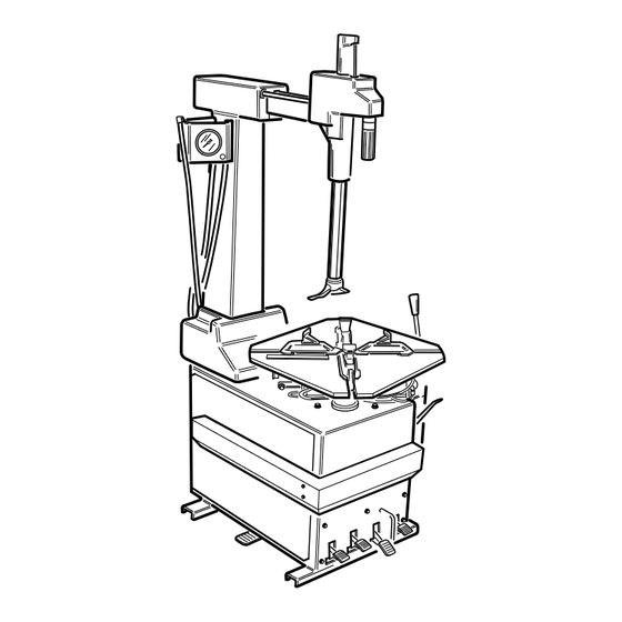
- Page 116 PROMAXX 8200...
- Page 120 PROMAXX 10”-20” 13”-23” 8240 PROMAXX 14”-24” min 17” 8240...
- Page 125 Cod. 430710C2...
- Page 126 Fig. 27 Cod. 446694_2...
- Page 127 Fig. 27 Cod. 4-104805A PROMAXX 8200-2 PROMAXX 8240-2...
- Page 128 Cod. 4-102875 PROMAXX 8200...
- Page 129 Cod. 4-102876 PROMAXX 8200 FI...
- Page 130 Cod. 4-102877 PROMAXX 8240 PROMAXX 8200-3...
- Page 131 Cod. 4-102878 PROMAXX 8240 FI...
- Page 134 DE - EG – Konformitätserklärung - EU – Konformitätserklärung * ES - Declaración EC de conformidad - Declaración UE de conformidad * Quale fabbricante dichiara che il prodotto: PROMAXX 8200 – PROMAXX 8240 al quale questa dichiarazione si riferisce e di cui abbiamo costituito e deteniamo il relativo fascicolo tecnico è...
Need help?
Do you have a question about the PROMAXX 8200 and is the answer not in the manual?
Questions and answers