Table of Contents
Advertisement
Quick Links
1
SERVICE MANUAL
Level 1&2
RM-675 / RM-691
Transceiver characteristics
Band
GSM 850/900/1800/1900
WCDMA 850/900/1700/1900/2100 (RM-675)
WCDMA 850/900/1700/2100 (RM-691)
Display:
3.5-inch nHD resolution (640 x 360), OLED
Camera:
8 Mpix full focus camera, dual LED flash, 10x
Digital zoom
Operating System:
Symbian^3
Connections:
WCDMA DL 384 kbps HSDPA 10 Mbps; UL 384 kbps
HSUPA 2 Mbps
GSM CS data 9.6 kbps / 14.4 kbps / HSCSD MSC6
GSM GPRS class 32, GSM EGPRS class 32, DTM 11
WLAN IEEE802.11 b/g/n with UPnP support
USB 2.0 high-speed through micro USB connector
Bluetooth wireless technology 2.1 + EDR
Nokia 3.5 mm AV connector for audio and TV
Transceiver with BL-5K battery pack
Talk time
GSM:
Up to 7.8 hours
WCDMA:
Up to 4.9 hours
Note:
Talk times are dependent on network parameters
and phone settings
Conf idential | Copyright © 2011 Nokia | A ll rights reserved
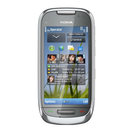
Nokia C7-00
RM-675 / RM-691
Service Manual Level 1&2
Standby
GSM:
Up to 632 hours
WCDMA:
Up to 546 hours
Version 6.0
Advertisement
Table of Contents

Related Manuals for Nokia RM-691


Summary of Contents for Nokia RM-691
- Page 1 Up to 7.8 hours Up to 632 hours WCDMA: WCDMA: Up to 4.9 hours Up to 546 hours Note: Talk times are dependent on network parameters and phone settings Conf idential | Copyright © 2011 Nokia | A ll rights reserved Version 6.0...
-
Page 2: Table Of Contents
BATTERY INFORMATION..............................8 EXPLODED VIEW ................................. 9 SERVICE DEVICES ................................10 SOFTWARE UPDATE................................11 DISASSEMBLY INSTRUCTIONS ............................12 10. ASSEMBLY INSTRUCTIONS ............................... 21 11. SOLDER COMPONENTS ..............................32 Conf idential | Copyright © 2011 Nokia | A ll rights reserved Version 6.0... - Page 3 Updated exploded view to match version 5.0 changes The purpose of this document is to help NOKIA service levels 1 and 2 workshop technicians to carry out service to NOKIA products. This Service Manual is to be used only by authorized NOKIA service suppliers, and the content of it is confidential.
-
Page 4: Copyright
Nokia operates a policy of continuous development. Nokia reserves the right to make changes and improvements to any of the products described in this document without prior notice. Under no circumstances shall Nokia be responsible for any loss of data or income or any special, incidental, consequential or indirect damages howsoever caused. -
Page 5: Warnings And Cautions
3. Use only approved components as specified in the parts list. 4. Ensure all components, modules screws and insulators are correctly re–fitted after servicing and alignment. 5. Ensure all cables and wires are repositioned correctly Conf idential | Copyright © 2011 Nokia | A ll rights reserved Version 6.0... -
Page 6: Esd Protection
ESD protected spare part packages MUST NOT be opened/closed out of an ESD Protected Area. For more information and local requirements about ESD protection and ESD Protected Area, contact your local Nokia After Market Services representative. Conf idential | Copyright © 2011 Nokia | A ll rights reserved Version 6.0... -
Page 7: Care And Maintenance
All of the above suggestions apply equally to the product, battery, charger or any accessory. Conf idential | Copyright © 2011 Nokia | A ll rights reserved Version 6.0... -
Page 8: Battery Information
Batteries’ performance is particularly limited in temperatures well below freezing. Do not dispose batteries in a fire! Dispose of batteries according to local regulations (e.g. recycling). Do not dispose as household waste. Conf idential | Copyright © 2011 Nokia | A ll rights reserved Version 6.0... -
Page 9: Exploded View
ANTENNA HOUSING I0018 I0023 SCREW TORX+ 4 I0025 BATTERY COVER I0026 Only available Not reuseable Repair/swap Ver. 3.0 as assembly after removal only in level 3 Conf idential | Copyright © 2011 Nokia | A ll rights reserved Version 6.0... -
Page 10: Service Devices
“Recommended service equipment” document on Nokia BL-5K Battery Online. SS-210 Camera Removal Tool SS-250 Display Removal Tool SS-231 RF Connector Disassembly/Assembly Tool Conf idential | Copyright © 2011 Nokia | A ll rights reserved Version 6.0... -
Page 11: Software Update
To use the FLS-5 Flash Dongle, follow the user guide inside the sales package. Please check always for the latest version of flash software, which is available on Nokia Online. Conf idential | Copyright © 2011 Nokia | A ll rights reserved... -
Page 12: Disassembly Instructions
5) Remove the BATTERY COVER. If there is a battery 6) Unscrew the two TORX+ size 4 screws in the order inserted, remove it also. shown. Do not use them again! Conf idential | Copyright © 2011 Nokia | A ll rights reserved Version 6.0... - Page 13 11) Unscrew the two TORX+ size 6 screws in the 12) Release the A-COVER by sliding it very gently to order shown. Do not use them again. Discard them. the direction shown. Conf idential | Copyright © 2011 Nokia | A ll rights reserved Version 6.0...
- Page 14 SS-250. 17) Carefully push in the SS-250, but be aware not to 18) Lift up the SS-250 and turn the DISPLAY over. damage the MICROPHONE. Conf idential | Copyright © 2011 Nokia | A ll rights reserved Version 6.0...
- Page 15 22) Use the SS-93 to release the CHASSIS. Note that CHASSIS ASSEMBLY is Level 3 service level. 23) Lift up the CHASSIS. 24) Use a DC plug to remove the DC JACK. Conf idential | Copyright © 2011 Nokia | A ll rights reserved Version 6.0...
- Page 16 29) Use the SS-93 to release the DISPLAY connector. 30) Remove the DISPLAY. While opening the connector, be careful not to damage the connector or any nearby components. Conf idential | Copyright © 2011 Nokia | A ll rights reserved Version 6.0...
- Page 17 34) Lift up the MAIN ANTENNA connector. connector. 35) Lock the SS-231 to the bottom MAIN ANTENNA 36) Lift up the bottom MAIN ANTENNA connector. connector. Conf idential | Copyright © 2011 Nokia | A ll rights reserved Version 6.0...
- Page 18 41) Use the AV plug to lever out the AV JACK. 42) Remove the AV JACK with the tweezers. Do not use it again. Discard it. Conf idential | Copyright © 2011 Nokia | A ll rights reserved Version 6.0...
- Page 19 46) Use the SS-93 to release the second clip holding bottom end of the ENGINE BOARD. the ENGINE BOARD. 47) Remove the ENGINE BOARD. 48) Use the SS-210 to remove the CAMERA MODULE. Conf idential | Copyright © 2011 Nokia | A ll rights reserved Version 6.0...
- Page 20 52) Remove the IHF SPEAKER GASKET with the dental Discard it. tool. Do not use it again. Discard it. 53) Nokia C7-00 disassembly is now complete. -END OF DISASSEMBLY- Conf idential | Copyright © 2011 Nokia | A ll rights reserved Version 6.0...
-
Page 21: Assembly Instructions
5) Press the CAMERA MODULE down carefully with the the shown clip is on the same side as the guiding SS-93 to attach the camera retaining clips. notch. Conf idential | Copyright © 2011 Nokia | A ll rights reserved Version 6.0... - Page 22 10) Press the IHF SPEAKER down carefully with the 11) Remove the camera lens protective film with the SS-93 to activate the adhesive. tweezers. Conf idential | Copyright © 2011 Nokia | A ll rights reserved Version 6.0...
- Page 23 ENGINE BOARD and is not damaged. 16) Close the USB DOOR. 17) Connect the SIM CARD READER connector with the SS-93. Be careful not to damage the connector or components nearby! Conf idential | Copyright © 2011 Nokia | A ll rights reserved Version 6.0...
- Page 24 22) Lock the MAIN ANTENNA to its place by pressing 23) Lock the SS-231 to the shorter of the two MAIN down with the SS-93. ANTENNA connectors as shown in the picture. Conf idential | Copyright © 2011 Nokia | A ll rights reserved Version 6.0...
- Page 25 MAIN ANTENNA connector. 28) Attach the connector with the SS-231. 29) Place the MAIN ANTENNA connector cable into the first clip with the tweezers. Conf idential | Copyright © 2011 Nokia | A ll rights reserved Version 6.0...
- Page 26 34) Push down the DC JACK to activate the adhesive. 35) Open the two EARPIECE HOLDER clips with the SS- 93 and turn the CHASSIS over. Conf idential | Copyright © 2011 Nokia | A ll rights reserved Version 6.0...
- Page 27 41) Place the top side of the CHASSIS next to the B- tweezers as shown. COVER so that the CHASSIS clip is placed under the B- COVER clip. Set down the CHASSIS. Conf idential | Copyright © 2011 Nokia | A ll rights reserved Version 6.0...
- Page 28 46) Tighten these three TORX + size 6 screws to the 47) Remove the adhesive protective film from the torque of 12,5 Ncm in the order shown. CHASSIS. Conf idential | Copyright © 2011 Nokia | A ll rights reserved Version 6.0...
- Page 29 53) Place the A-COVER as shown and make sure that the flex! the A-COVER flex does not go between the edges of the A-COVER and the B-COVER. Conf idential | Copyright © 2011 Nokia | A ll rights reserved Version 6.0...
- Page 30 59) Press the A-COVER CHIN from the top to lock the 58) Push the A-COVER CHIN into place. two clips on the bottom end. Conf idential | Copyright © 2011 Nokia | A ll rights reserved Version 6.0...
- Page 31 62) Then set down the bottom end and press it 63) Finally, remove the LOCK KEY protective film. gently to lock it. 64) The Nokia C7-00 assembly procedure is now complete. -END OF ASSEMBLY- Conf idential | Copyright © 2011 Nokia | A ll rights reserved Version 6.0...
-
Page 32: Solder Components
X7501 X7000 X2403 X1600 X3302 X3303 X2400 X2700 X7001 BOTTOM X1497 X1498 X1496 X6304 F3301 X3300 V2401 F3300 X6501 S2401 X7500 X6500 X6203 X6204 Ver. 1.0 Conf idential | Copyright © 2011 Nokia | A ll rights reserved Version 6.0...
Need help?
Do you have a question about the RM-691 and is the answer not in the manual?
Questions and answers