Advertisement
Quick Links
intelligent motion systems, inc.
Excellence in Motion
FULL PRODUCT NAME
QUICK REFERENCE
QUICK REFERENCE
370 N. MAIN ST., PO BOX 457, MARLBOROUGH, CT 06447
PH: (860) 295-6102, FAX: (860) 295-6107
Internet: www.imshome.com, E-Mail: info@imshome.com
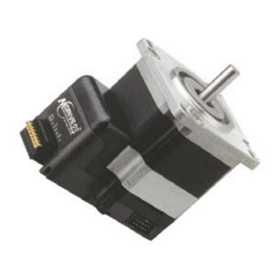
M D r i v e 2 3 M o t i o n C o n t r o l Q u i c k R e f e r e n c e G u i d e
The primary function of this guide is to acquaint the user with the spec i -
fi ca tions, basic wiring and confi guration of the MDrive23 Mo tion Control.
The product man u al in PDF for mat is on the IMS Product CD or may be
down load ed from the IMS web site at www.imshome.com.
The product manual also contains a "Getting Started" document to guide
you in rapidly setting up and turning your MDrive23.
N o t e s a n d W a r n i n g s
Please observe the following when handling, connecting and using your
MDrive23. Failure to observe these points may result in damage to the
product. NOTE: The electronics are not removable from the motor in the
fi eld. The entire unit must be sent back to the factory for repair. All war-
ranty and disclaimer information is located in the full product manual and
should be referenced for more information.
L a y o u t a n d I n t e r f a c e G u i d e
Logic level cables must not run parallel to power cables. This will introduce
noise and make the system un re li able.
Logic level cables must be shielded to reduce the risk of EMI induced
noise. The shield must be grounded at the signal source to AC ground.
The opposite end of the shield must not be connected which allows it to
fl oat and act as a drain.
The supply to the driver must be a twisted pair. If more than one driver is
being connected, run separate leads to each driver.
G e n e r a l S p e c i f i c a t i o n s
E l e c t r i c a l
Input Voltage (+V) Range* ..................................... +12 to +48 VDC
Analog Input
Resolution .....................................................................10 Bit
Voltage Range ...................................0 to +5 VDC or 4 - 20 mA
G e n e r a l P u r p o s e I / O
Number/Type ..................................................... 4/Open Collector
Logic Range .......................................................... +5 to +24 VDC
Output Sink Current ..........................................................700 mA
Protection ......................... Over Temp, Short Circuit, Inductive Clamp
Communication Type ..........................................................RS-485
Baud Rate ..............................................................4800 to 115K
*Graph at right illustrates
power supply current require-
ments (MAX) per MDrive23.
Actual power supply current
will depend on voltage and
load.
M o t i o n S p e c i f i c a t i o n s
Resolution – Open Loop Confi guration
# of Settings................................................................... 14
Steps Per Rev........................ 400, 800, 1000, 1600, 2000,
Resolution – Closed Loop Confi guration (Optional)
Steps Per Rev........................................................... 51200
Encoder (Optional)
Type ......................................................... Internal, Mag net ic
Resolution ............................. 512 Lines/2048 Edges Per Rev
Counters
Type .............................................. Position, En cod er/32 Bits
Edge Rate (Max)......................................................... 5 MHz
Velocity
Range................................. +/- 5,000,000 Steps Per Second
Resolution ......................................0.5961 Steps Per Second
Accel/Decel
Range........................................ 1.5 x 10
Resolution .........................................90.9 Steps Per Second
Rev. 072705
TM
TM
TM
MOTION CON TROL
3200, 5000, 6400, 10000, 12800,
25000, 25600, 50000, 51200
9
Steps Per Second
© Intelligent Motion Systems, Inc.
S o f t w a r e S p e c i f i c a t i o n s
Program and Data Storage .............................................Nonvolatile
User Registers............................................................... (4) 32 Bit
Math Functions .........................................+, -, ×, ÷, <, >, =, <=, >=,
Branch Functions .................................... Branch & Call (conditional)
Predefi ned I/O Functions
Inputs ............Home, Limit Plus, Limit Minus, Go, Soft Stop,
Outputs....................... Moving, Fault, Stall, Velocity Change
Trip Functions ................................... Trip on Input & Trip on Position
Party Mode Addresses............................................................. 62
Encoder Functions .......................................Stall Detection, Position
WARNING! When using the MDrive Motion Control with optional
internal magnetic encoder, no axial force may be applied to the
motor shaft without use of a load bearing isolation coupling.
R e c o m m e n d e d I M S P o w e r S u p p l i e s
I P 4 0 4 U n r e g u l a t e d L i n e a r S u p p l y
Input Range
120 VAC Versions ...................................... 102-132 VAC
240 VAC Versions ...................................... 204-264 VAC
Output
No Load Output Voltage*......................43 VDC @ 0 Amps
Continuous Output Rating* ...................32 VDC @ 2 Amps
Peak Output Rating*............................26 VDC @ 4 Amps
I S P 2 0 0 - 4 U n r e g u l a t e d S w i t c h i n g S u p p l y
Input Range
120 VAC Versions ...................................... 102-132 VAC
240 VAC Versions ...................................... 204-264 VAC
Output
No Load Output Voltage*......................41 VDC @ 0 Amps
Continuous Output Rating* ................38 VDC @ 1.5 Amps
Peak Output Rating*............................35 VDC @ 3 Amps
* All measurements were taken at 25°C, 120 VAC, 60 Hz.
A char ac ter is tic of all motors is back EMF. Back EMF is a source of cur-
rent that can push the output of a power supply beyond the maximum
op er at ing voltage of the driver. As a result, damage to the stepper
driv er could occur over a period of time. Care should be taken so that
the back EMF does not exceed the maximum input voltage rating of the
MDrive23.
R e c o m m e n d e d P o w e r S u p p l y C o n n e c t i o n s
M D r i v e w i t h 7 P i n P l u g g a b l e C o n n e c t o r
Unregulated
Linear or
Switching
Power Supply
Power
Ground
+VDC
Shield to
Earth Ground
M D r i v e w i t h F l y i n g L e a d s
Unregulated
Linear or
Shielded Twisted Pair
Switching
Power Supply
Power
Ground
+VDC
Shield to
Earth Ground
T h e r m a l S p e c i f i c a t i o n s
The MDrive consists of two core components, a drive and a motor.
Close attention must be paid to the thermal environment where the
device is used. The maximum temperatures are:
Maximum Heat Sink Temperature .......................................... 85° C
Maximum Motor Temperature............................................. 100° C
2
2
See the complete MDrive Motion Control Product Manual
on the IMS Product CD or at www.imshome.com
& (AND), l (OR), ^ (XOR), ! (NOT)
Pause, Jog Plus, Jog Minus, Analog In
Maintenance, Find Index
P1
White/Yellow I/O1
White/Orange I/O2
White/Violet I/O3
White/Blue I/O4
Green Analog Input
–
+
Ferrite
π Type RFI Filter
Beads
≥ Required Current
MDrive Motion Control with
12" (30cm) Flying Leads (P1)
For More Information:
Pin1
OPTO
SPLY
NC
SCLK
DIR
EN
GND
GND
+V
+V
P1
Advertisement

Related Manuals for IMS MDrive23


Summary of Contents for IMS MDrive23
- Page 1 fi ca tions, basic wiring and confi guration of the MDrive23 Mo tion Control. Peak Output Rating*......35 VDC @ 3 Amps The product man u al in PDF for mat is on the IMS Product CD or may be * All measurements were taken at 25°C, 120 VAC, 60 Hz.
- Page 2 AWG 20 +V (+12 to +48 VDC) (Ø 5.0) WARNING! The maximum +48 VDC Input Voltage of the MDrive23 includes motor back EMF, power supply ripple and high line. WARNING! DO NOT connect or disconnect power leads or motor leads when power is applied! Disconnect the AC power side to power down the 1.856 ±0.008 SQ.
Need help?
Do you have a question about the MDrive23 and is the answer not in the manual?
Questions and answers