Advertisement
Quick Links
intelligent motion systems, inc.
Excellence in Motion
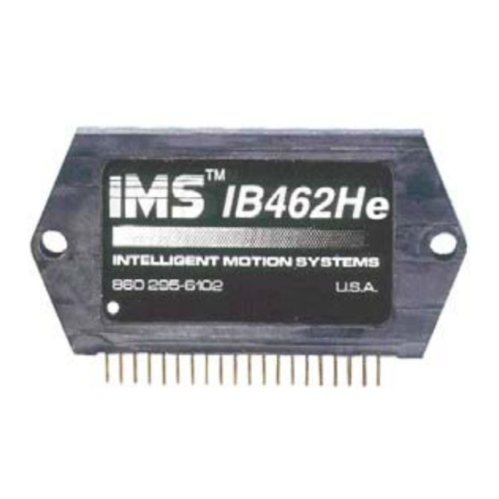
IB462He
BIPOLAR STEPPING MOTOR DRIVER
QUICK REFERENCE
370 N. MAIN ST., PO BOX 457, MARLBOROUGH, CT 06447
PH: (860) 295-6102, FAX: (860) 295-6107
Internet: www.imshome.com, E-Mail: info@imshome.com
I B 4 6 2 H e Q u i c k R e f e r e n c e / I n s t a l l a t i o n G u i d e
The primary function of this guide is to acquaint the user with the
specifications, basic wiring and configuration of the IB462He
Bipolar Stepping Motor Driver. The full product manual is available
in Acrobat PDF format on the IMS Product CD. It also may be
downloaded from the IMS web site at www.imshome.com.
N o t e s A n d W a r n i n g s
Please observe the following when handling, connecting and using
your IB462He Driver and INT-462 Interface Board. Failure to
observe these points may result in damage to the drive. All
warranty and disclaimer information is located in the full product
manual and should be referenced for more information.
The IB462He and INT-462 components are sensitive to
Electrostatic Discharge (ESD). All handling should be done
at an ESD protected workstation.
Hazardous Voltage Levels may be present if using an open
frame power supply to power the IB462He and INT-462.
The Power Supply output voltage must not exceed the
maximum input voltage of the IB462He and INT-462.
Do not apply power to the IB462He without proper heatsinking
or cooling. The maximum rear plate temperature of the
IB462He is 70°C!
The rear mounting surface of the driver contains various
voltages and must be kept isolated when attached to a
conductive surface!
Do not connect or disconnect power leads or motor leads when
power is applied! Disconnect the AC power side to power down
the DC power supply.
For battery operated systems, conditioning measures should
be taken to prevent device damage caused by in-rush current
draws, transient arcs and high voltage spikes.
I B 4 6 2 H e M e c h a n i c a l S p e c i f i c a t i o n s
Dimensions in Inches (mm)
2.120
(58.85)
1.895
(48.13)
2X Ø 0.150
(3.81)
2X R 0.125
(3.18)
21 X 0.020 (0.5)
SQ. PIN
0.79
(2.0)
Revision 090205
TM
TM
0.585
(14.86)
1.169
(29.7)
0.189
0.270
(4.8)
(6.86)
© Intelligent Motion Systems, Inc.
E l e c t r i c a l S p e c i f i c a t i o n s
S
p
e
c
f i
c i
t a
o i
n I
p
t u
V
o
a t l
g
e
P
h
a
s
e
O
u
p t
t u
C
r u
e r
t n
Q
u
e i
c s
e
t n
C
r u
e r
t n
+ (
) V
Q
u
e i
c s
e
t n
C
r u
e r
t n
+ (
5
V
C
r u
e r
t n
A
d
u j
t s
n I
p
t u
V
o
L
o
w
L
e
v
l e
n I
p
t u
V
o
a t l
g
H
g i
h
L
e
v
l e
n I
p
t u
V
o
a t l
g
L
o
w
L
e
v
l e
n I
p
t u
C
r u
e r
t n
L
o
w
L
e
v
l e
n I
p
t u
C
r u
e r
t n
H
g i
h
L
e
v
l e
n I
p
t u
C
r u
e r
t n
E
n
a
b
e l
L
o
w
L
e
v
l e
n I
p
t u
E
n
a
b
e l
H
g i
h
L
e
v
l e
n I
p
t u
n I
p
t u
P
l l u
u -
p
R
e
s
s i
a t
c n
n I
p
t u
P
l l u
u -
p
R
e
s
s i
a t
c n
T h e r m a l S p e c i f i c a t i o n s
Ambient Temperature ......................................................... 0 to +50°C
Storage Temperature .......................................................... -40 to +125°C
Maximum Plate Temperature* ................................... +70°C
* Additional cooling may be required to limit plate temperature to +70°C.
R e c o m m e n d e d H o l e P a t t e r n F o r P C B M o u n t i n g
Dimensions in Inches (mm)
0.079 TYP
(2.00 TYP)
P o w e r I n t e r f a c e
M o t o r S u p p l y
Pins 13&14 (+V) and Pins 15&16 (Ground) are used to connect
the DC motor power to the IB462He Driver. Two local capacitors
must be connected to Pins 13&14 and Pins 15&16. These
capacitors must be located as close to the IB462He motor
supply input pins as possible to ensure stable operation.
+ 5 V D C I n p u t
The IB462He requires an external +5 VDC power supply which is
connected between Pin 5 (+V) and ground. The +5 VDC supply
ground and the motor supply ground must not be connected to
each other at the power supplies. The +5 VDC ground must be
connected to the ground pin of the electrolytic capacitor.
R e q u i r e d C a p a c i t o r s
The first capacitor is a low impedance, aluminum electrolytic. The
continuous operating voltage of the capacitor must exceed the
maximum supply voltage as well as any back EMF voltage
generated by the motor. The capacitance should be 150 µF for
0.284
each amp of peak phase output current.
(7.21)
Example: 1.4A peak @ 40 VDC x 150 µF = 220 µF 60V.
A 0.1 µF 100V capacitor must be used to filter high frequency
noise. It must be placed between the motor power input pins
13&14 (+V) and 15&16 (ground) and the electrolytic capacitor.
The continuous operating voltage of this capacitor must exceed
the maximum supply voltage as well as any back EMF voltage
0.065
generated by the motor.
(1.65)
The +5 VDC supply requires a 22 µF 10V Tantalum capacitor to
be installed as close to the IB462He Driver as possible between
Pin 5 (+5V) and ground.
n
T
e
t s
C
o
n
d
t i
o i
n
P
r e
P
h
a
s
e
O
u
p t
u
s t
F
o l
t a
n i
g
n I
p
u
) t
O
u
p t
u
s t
F
o l
t a
n i
g
a t l
g
e
e
S
C
L
, K
I D
, R
H
, F /
R
e
s
t e
e
S
C
L
, K
I D
, R
H
, F /
R
e
s
t e
S
C
L
, K
I D
, R
H
, F /
E
n
a
b
e l
R
e
s
t e
n I
p
t u
O
n
y l
S
C
L
, K
I D
, R
H
, F /
E
n
a
b
e l
V
o
a t l
g
e
E
n
a
b
e l
n I
p
t u
O
n
y l
V
o
a t l
g
e
E
n
a
b
e l
n I
p
t u
O
n
y l
e
S
C
L
, K
I D
, R
H
, F /
E
n
a
b
e l
e
R
e
s
t e
n I
p
t u
O
n
y l
1.560
(39.62)
0.78 (19.81)
Reference
PIN #1
C L
0.79 (20.10)
Reference
1.580
(40.13)
5
6
7
8
9 10 11 12 13 14 15 16
22µF
10V
Tantalum
+
_
+
+5VDC
Supply
M
i
. n
T
y
. p
M
a
. x
U
n
t i
1
2
4
8
V
0
1 .
2
A
4
m
A
5
0
8
0
m
A
1
0 .
V
0
6 .
V
2
5
V
1 -
2 .
m
A
µA
2 -
0
0
µA
1
0
1
3 .
V
2
5
V
4
5 .
4
7 .
4
9 .
kΩ
5
0
5
1
5
2
kΩ
Range
Ø 0.166 +.003/-0
(Ø 4.22 +0.8/-0)
2 PLACES
0.219
(5.56)
0.064 PAD, 0.031 HOLE
(1.6 PAD, 0.78 HOLE)
.
0 1µF
100V
Additional
Electrolytic
Capacitor
_
+
Motor
Supply
Advertisement

Related Manuals for IMS IB462He


Summary of Contents for IMS IB462He
- Page 1 Bipolar Stepping Motor Driver. The full product manual is available (39.62) (Ø 4.22 +0.8/-0) 2 PLACES in Acrobat PDF format on the IMS Product CD. It also may be 0.78 (19.81) Reference downloaded from the IMS web site at www.imshome.com.
- Page 2 M o u n t i n g t h e I B 4 6 2 H e Heat sinking and the use of the included insulating thermal pad are ABSOLUTELY REQUIRED for the IB462He driver at all power levels. Below are some examples of mounting configurations.
Need help?
Do you have a question about the IB462He and is the answer not in the manual?
Questions and answers