Advertisement
Quick Links
VISAGE SCREEN SYSTEM - TWO SIDED (FLAT PACK)
NOTE: Ensure that all relevant personnel read the points listed below and that a copy is passed on to staff involved
with the installation. Please also refer to the 'Manual Handling Operations Regulations 1992' during the
handling of the product and materials used for installation. The total weight of this product is 40kg (770L) and
46kg (1280L).
TOOLS REQUIRED:
13mm Spanner
Hand Drill with Pozi Drill Bit
10mm x 150mm Masonry Drill Bit
Rubber Mallet
Hammer
KIT CONTENTS:
ITEM A
Side Panel
ITEM B
Front Panel
ITEM C
5mm x 20mm Chipboard Screw
ITEM D
M10 x 120mm Ground Fixing Bolt
ITEM E
Support Leg
ITEM F
Side Skirting (optional)
ITEM G
Front Skirting (optional)
ITEM H
Repair Washer M5 x 25mm S/S
(optional)
NOTE: Some xings apply to the optional skirting
so there may be less xings than stated.
A
E
We recommend that a risk assessment is undertaken to identify an appropriate location for your waste
collection and recycling units. In order to reduce risk, some organisations decide to place the units a minimum
of 5 metres away from buildings. Any potential risk can be further reduced by maintaining a regime of regularly
emptying the unit.
TM
ASSEMBLY & FIXING INSTRUCTION LEAFLET
x1
x1
x1
x1
x1
B
F
17mm Spanner
6mm Allen Key
770L 1280L
x1
x1
x1
x1
x19
x21
x5
x5
x2
x2
x1
x1
x1
x1
x12
x14
C
P. 1
x2
x1
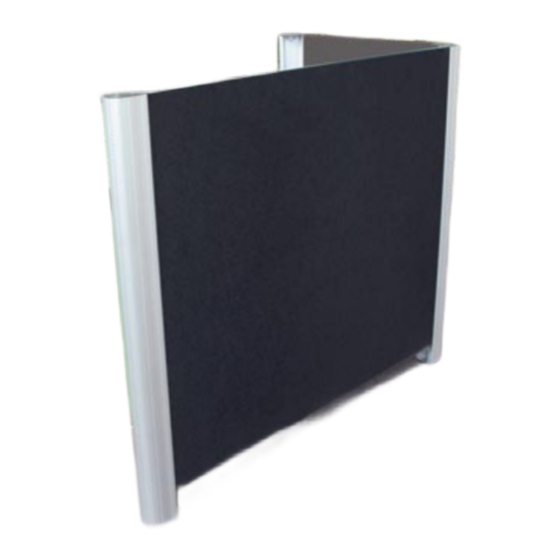
Assembled
Two Sided
Screen
(Right Hand
770 L)
FRONT
D
G
SIDE
H
Advertisement

Related Manuals for Glasdon VISAGE

Summary of Contents for Glasdon VISAGE
- Page 1 VISAGE SCREEN SYSTEM - TWO SIDED (FLAT PACK) ASSEMBLY & FIXING INSTRUCTION LEAFLET NOTE: Ensure that all relevant personnel read the points listed below and that a copy is passed on to staff involved with the installation. Please also refer to the ‘Manual Handling Operations Regulations 1992’ during the handling of the product and materials used for installation.
- Page 2 Step 1: Assembly of Two Sided Screen (Right Hand) Hold panel (B) up to the right Using rubber mallet (so not to Tap the top of the extrusion to hand extrusion on panel (A) damage the extrusions) tap the ensure the board is level up to the ensuring that the feet with the side at the top of the extrusion so top of the extrusion cover cap.
- Page 3 Step 3: Ground Fixing (Concrete In) The xing bolts (D) MUST appear as Tighten bolt using 17mm Using a 10mm masonry drill bit, above with the nut and washer at spanner. Repeat Figs 10-12 drill through the hole in the spigot the top of the bolt.
- Page 4 Replacement components are available direct from GLASDON. BLACKPOOL Glasdon U.K. Ltd reserves the right to alter specifications without prior notice. GLASDON cannot be held responsible for claims arising from incorrect installation, unauthorised modifications or misuse of Lancashire FY4 4UL the product.
Need help?
Do you have a question about the VISAGE and is the answer not in the manual?
Questions and answers