Table of Contents
Advertisement
Quick Links
Technical Explanation
SEMITOP E2 1200V
MLI Inverter Board
1. Introduction ............................................................................................................................... 1
1.1 Features .............................................................................................................................. 2
1.2 Hardware of the SEMITOP E2 1200V MLI Inverter Board ............................................................ 2
2. Safety Instructions ..................................................................................................................... 4
3. Technical Data ........................................................................................................................... 6
3.1 Inverter board block diagram .................................................................................................. 6
3.2 Electrical and mechanical characteristics .................................................................................. 6
3.3 Integrated functions .............................................................................................................. 9
3.3.1
Gate protection ............................................................................................................. 10
3.3.2
V
diodes .............................................................................................................. 10
3.3.3
Active clamping ............................................................................................................ 10
3.4 Board description ................................................................................................................ 10
3.4.1
Plugs for driver board adaptation .................................................................................... 11
3.4.2
Active clamping ............................................................................................................ 11
3.4.3
Plugs for driver board adaptation .................................................................................... 12
4. User Interface .......................................................................................................................... 13
4.1 Driver board interface .......................................................................................................... 13
4.2 DC and AC interface ............................................................................................................ 13
5. Restrictions and Requirements ................................................................................................... 14
5.1 Switching pattern of (T)MLI modules ..................................................................................... 14
5.2 Error treatment ................................................................................................................... 14
5.3 Design limits active clamping ................................................................................................ 14
5.4 Design limits switching frequency .......................................................................................... 14
5.5 Design limits ambient temperature ........................................................................................ 14
5.6 SEMIKRON assembly ........................................................................................................... 14
1.
Introduction
SEMIKRON set up a 3-phase inverter board for operating SEMITOP E2 1200V MLI modules for evaluation
purposes. The SEMITOP E2 1200V MLI Inverter Board ("inverter board") is designed to operate with three
SKYPER12 (T)MLI Driver Boards (also a SEMIKRON Application Sample; Technical Explanation available),
one per phase leg. It is designed to operate the module up to a DC-link voltage of 1500V (limited by
insulation coordination) at a maximum switching frequency of 30kHz (limited by insulation coordination);
i.e. higher switching frequencies are possible with a revision of the insulation coordination and the
limitation of the gate driver needs to be taken into account.
Three driver boards (SKYPER 12 (T)MLI Driver Board) are mounted to the inverter board, one per phase
leg (one driver operates switches T1 and T2, the other operates switches T3 and T4). The 1200V MLI phase
leg is split in two SEMITOP E2 module housings, one inheriting switches T1, D1, T2, D2 and D5, the other
housing T3, D3, T4, D4 and D6 (see Figure 1).
The inverter board provides active clamping diodes for all switches and V
outer switches T1 and T4 utilizing the driver boards' protection functionality. Further all modules have a
built-in NTC sensor (six in total) which are all monitored.
Please read also the Technical Explanation - SKYPER12 (T)MLI Driver Board for detailed information on the
driver boards used together with the inverter board described in this document.
© by SEMIKRON / 2018-12-03 / Technical Explanation / SEMITOP E2 1200V MLI Inverter Board
PROMGT.1026/ Rev.7/ Template Technical Explanation
Revision:
Issue date:
Prepared by:
Reviewed by:
Approved by:
Keyword: MLI, IGBT driver, inverter, Application Sample, 451375
03
2018-12-03
Ingo Rabl
-
Ulrich Nicolai
detection diodes for the
CE,desat
Page 1/18
Advertisement
Table of Contents

Related Manuals for SEMIKRON SEMITOP E2

Summary of Contents for SEMIKRON SEMITOP E2
-
Page 1: Table Of Contents
(one driver operates switches T1 and T2, the other operates switches T3 and T4). The 1200V MLI phase leg is split in two SEMITOP E2 module housings, one inheriting switches T1, D1, T2, D2 and D5, the other housing T3, D3, T4, D4 and D6 (see Figure 1). -
Page 2: Features
This Application Sample is dedicated to both universities and professional development engineers. It offers an easy way to set up a three phase inverter with SEMITOP E2 MLI modules and 2L drivers for a DC-link voltage up to 1500V. Performance tests can be run to prove the possibility of operation at high DC-link voltages and the high output power. - Page 3 An appropriate heatsink (and mechanical support for the inverter board) needs to be provided by the user (see also chapter 3.2). © by SEMIKRON / 2018-12-03 / Technical Explanation / SEMITOP E2 1200V MLI Inverter Board Page 3/18 PROMGT.1026/ Rev.7/ Template Technical Explanation...
-
Page 4: Safety Instructions
Safety Instructions The SEMITOP E2 1200V MLI Inverter Board bares risks when put in operation. Please carefully read and obey the following safety instructions to avoid harm or damage to persons or gear. Table 1: Safety instructions In operation the SEMITOP E2 1200V MLI... - Page 5 5) Cover or close of nearby live parts! To energize, apply in reverse order! Please follow the safety regulations for working safe with the SEMITOP E2 1200V MLI Inverter Board. Table 3: No access for people with active implanted cardiac devices! Operating the Application Sample may go along with electromagnetic fields which may disturb cardiac devices.
-
Page 6: Technical Data
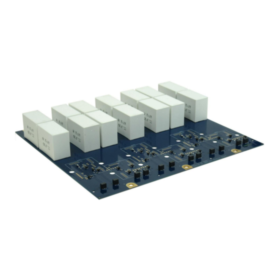
MLI Inverter Board. The overall responsibility for a proper insulation coordination remains with the user. The inverter board is 300mm long and 330mm wide. Including SEMITOP E2 modules the total height is 60mm. © by SEMIKRON / 2018-12-03 / Technical Explanation / SEMITOP E2 1200V MLI Inverter Board Page 6/18 PROMGT.1026/ Rev.7/ Template Technical Explanation... - Page 7 Figure 5 shows the top side of the inverter board. Here the diodes for the active clamping circuit are located. The SEMITOP E2 power semiconductor modules are mounted on the bottom side of the inverter board (Figure 6). © by SEMIKRON / 2018-12-03 / Technical Explanation / SEMITOP E2 1200V MLI Inverter Board Page 7/18 PROMGT.1026/ Rev.7/ Template Technical Explanation...
- Page 8 The support posts must be able to isolate the DC-link voltage from the heatsink, i.e. no metal posts may be used. © by SEMIKRON / 2018-12-03 / Technical Explanation / SEMITOP E2 1200V MLI Inverter Board Page 8/18 PROMGT.1026/ Rev.7/ Template Technical Explanation...
-
Page 9: Integrated Functions
The driver board has some optional integrated safety functions to protect the power module from certain harmful conditions. © by SEMIKRON / 2018-12-03 / Technical Explanation / SEMITOP E2 1200V MLI Inverter Board Page 9/18 PROMGT.1026/ Rev.7/ Template Technical Explanation... -
Page 10: Gate Protection
The components that can be changed by the user on the inverter board are marked with different coloured frames in Figure 8. Figure 9 shows the positions exemplarily at phase V (the light blue dotted frame in © by SEMIKRON / 2018-12-03 / Technical Explanation / SEMITOP E2 1200V MLI Inverter Board Page 10/18... -
Page 11: Plugs For Driver Board Adaptation
U to phase V and by one from phase V to phase W. Example: X201 ⇒ upper half module phase U; X301 ⇒ upper half module phase V, X401 ⇒ upper half module phase W. Figure 9 shows also the position where the SEMIKRON SKYPER12 (T)MLI Driver Board can be plugged to the inverter board (dotted purple frame). -
Page 12: Plugs For Driver Board Adaptation
70°C and 150°C. The full characteristic can be found in the Technical Explanations of SEMITOP E or can be calculated from the formula given in the SEMITOP E2 datasheets [1]. Figure 11: SEMITOP E2 NTC characteristic (excerpt) 1000 [°C]... -
Page 13: User Interface
The cable shoes may not exceed the size of the DC contact areas in order not to reduce insulation distances. © by SEMIKRON / 2018-12-03 / Technical Explanation / SEMITOP E2 1200V MLI Inverter Board Page 13/18 PROMGT.1026/ Rev.7/ Template Technical Explanation... -
Page 14: Restrictions And Requirements
Switching pattern of (T)MLI modules A detailed explanation of the MLI switching pattern is given in the SEMIKRON Application Note AN-11001 [3]. Summed up always an inner IGBT (T2 or T3) must be switched on first, the corresponding outer IGBT (T1 or T4) after a short while, namely when the inner IGBT is entirely switched on. - Page 15 It is up to the customer to optimize user-changeable values according to the particular operation and do the necessary tests with these changes. © by SEMIKRON / 2018-12-03 / Technical Explanation / SEMITOP E2 1200V MLI Inverter Board Page 15/18...
- Page 16 Table 6: Part revisions for SEMIKRON tests ..................15 Table 7: Part values for SEMIKRON tests ..................15 © by SEMIKRON / 2018-12-03 / Technical Explanation / SEMITOP E2 1200V MLI Inverter Board Page 16/18 PROMGT.1026/ Rev.7/ Template Technical Explanation...
- Page 17 12 – rev5”, SEMIKRON Technical Explanation, 2017 ® [7] R. Agostini, “Technical Explanation SEMITOP – rev5”, SEMIKRON Technical Explanation, 2017 ® © by SEMIKRON / 2018-12-03 / Technical Explanation / SEMITOP E2 1200V MLI Inverter Board Page 17/18 PROMGT.1026/ Rev.7/ Template Technical Explanation...
- Page 18 SEMIKRON does not assume any liability arising out of the applications or use of any product; neither does it convey any license under its patent rights, copyrights, trade secrets or other intellectual property rights, nor the rights of others.
Need help?
Do you have a question about the SEMITOP E2 and is the answer not in the manual?
Questions and answers