Table of Contents
Advertisement
Quick Links
Advertisement
Table of Contents

Related Manuals for MULTIQUIP Whiteman CA5BC


Summary of Contents for MULTIQUIP Whiteman CA5BC
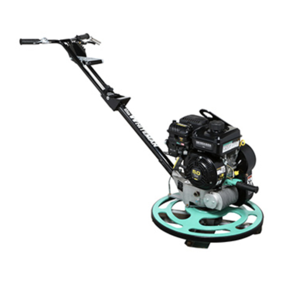
- Page 1 MODEL CA5BC WALK-BEHIND TROWEL (VANGUARD 5 HP GASOLINE ENGINE) Revision #1 (05/18/22) To find the latest revision of this publication or associated parts manual, visit our website at: www.multiquip.com THIS MANUAL MUST ACCOMPANY THE EQUIPMENT AT ALL TIMES. PN: 48235...
-
Page 2: Proposition 65 Warning
PROPOSITION 65 WARNING PAGE 2 — CA5BC WALK-BEHIND TROWEL • OPERATION MANUAL — REV. #1 (05/18/22) -
Page 3: Silicosis/Respiratory Warnings
SILICOSIS/RESPIRATORY WARNINGS WARNING WARNING SILICOSIS WARNING RESPIRATORY HAZARDS Grinding/cutting/drilling of masonry, concrete, metal and Grinding/cutting/drilling of masonry, concrete, metal and other materials with silica in their composition may give other materials can generate dust, mists and fumes off dust or mists containing crystalline silica. Silica is a containing chemicals known to cause serious or fatal basic component of sand, quartz, brick clay, granite and injury or illness, such as respiratory disease, cancer,... -
Page 4: Table Of Contents
TABLE OF CONTENTS CA5BC Walk-Behind Trowel Proposition 65 Warning ........... 2 Silicosis/Respiratory Warnings ........ 3 Table Of Contents ............ 4 Training Checklist ............ 5 Daily Pre-Operation Checklist ......... 6 Safety Information ..........7–12 Lifting And Transporting ......... 13 Specifications ............14 Dimensions ............ -
Page 5: Training Checklist
TRAINING CHECKLIST Training Checklist Description Date Read operation manual completely. Machine layout, location of components, checking of engine oil level. Fuel system, refueling procedure. Operation of controls (machine not running). Safety controls, safety stop switch operation. Emergency stop procedures. Startup of machine, engine choke. Maintaining a hover. -
Page 6: Daily Pre-Operation Checklist
DAILY PRE-OPERATION CHECKLIST Daily Pre-Operation Checklist Engine oil level Gearbox oil level Condition of blades Blade pitch operation Safety stop switch operation PAGE 6 — CA5BC WALK-BEHIND TROWEL • OPERATION MANUAL — REV. #1 (05/18/22) -
Page 7: Safety Information
SAFETY INFORMATION DO NOT operate or service the equipment before reading Potential hazards associated with the operation of this equipment will be referenced with hazard symbols which the entire manual. Safety precautions should be followed at all times when operating this equipment. may appear throughout this manual in conjunction with Failure to read and understand the safety safety messages. - Page 8 SAFETY INFORMATION SAFETY DECALS GENERAL SAFETY Decals associated with the safe operation of this equipment CAUTION are defi ned below: „ DO NOT operate this equipment without proper protective clothing, shatterproof glasses, respiratory protection, hearing protection, steel-toed boots and other protective WARNING devices required by the job or city and state regulations.
- Page 9 „ DO NOT use accessories or attachments that are not restricted. If the air fl ow is recommended by Multiquip for this equipment. Damage restricted it will cause injury to the equipment and/or injury to the user may result.
- Page 10 SAFETY INFORMATION ENGINE SAFETY CAUTION „ DO NOT stand on the trowel during operation. WARNING „ NEVER lubricate components or attempt service on a „ DO NOT place hands or fingers inside the engine running machine. compartment while the engine is running. „...
- Page 11 SAFETY INFORMATION FUEL SAFETY TRANSPORTING SAFETY DANGER WARNING „ DO NOT add fuel to the equipment if it is placed inside „ DO NOT allow any person or animal a truck bed with a plastic liner. The possibility exists of to stand underneath the equipment explosion or fi re due to static electricity.
- Page 12 SAFETY INFORMATION ENVIRONMENTAL SAFETY/DECOMMISSIONING EMISSIONS INFORMATION NOTICE NOTICE Decommissioning is a controlled process used to safely The gasoline engine used in this equipment has been retire a piece of equipment that is no longer serviceable. designed to reduce harmful levels of carbon monoxide If the equipment poses an unacceptable and unrepairable (CO), hydrocarbons (HC), and nitrogen oxides (NOx) safety risk due to wear or damage or is no longer cost...
-
Page 13: Lifting And Transporting
LIFTING AND TRANSPORTING LIFTING THE TROWEL Lifting Bail The lifting bail provides an optimal lift point for the trowel. WARNING When lifting the trowel onto a concrete slab, attach a chain Extra care should be taken when lifting the trowel. or rope to the lifting bail. -
Page 14: Specifications
SPECIFICATIONS Table 1. CA5BC Trowel Specifications Table 2. Vanguard Engine Specifications Number of Blades Model Vanguard 10V300 Clutch Type Centrifugal Type Single-cylinder, gasoline engine Ring Diameter 24 in. (610 mm) Bore × Stroke 2.44 in. × 2.2 in. (62 mm × 56 mm) Rotor Speed 70–130 rpm Displacement... -
Page 15: Dimensions
DIMENSIONS Figure 2. CA5BC Dimensions Dimensions Table 4. CA5BC (A) Height (Lifting Bail) 28.0 in. (711 mm) (B) Height (Handle) 36.3 in. (921 mm) (C) Width 24.0 in. (610 mm) (D) Length 61.2 in. (1,555 mm) CA5BC WALK-BEHIND TROWEL • OPERATION MANUAL — REV. #1 (05/18/22) — PAGE 15... -
Page 16: General Information
If the original engine manual becomes lost or damaged, please contact your nearest Multiquip dealer for a replacement. Drive System Power is transferred from the engine to the gearbox input shaft via a V-belt pulley drive system. The pulley engages a centrifugal clutch. - Page 17 NOTES CA5BC WALK-BEHIND TROWEL • OPERATION MANUAL — REV. #1 (05/18/22) — PAGE 17...
-
Page 18: Components (Trowel)
COMPONENTS (TROWEL) Figure 3. Trowel Components PAGE 18 — CA5BC WALK-BEHIND TROWEL • OPERATION MANUAL — REV. #1 (05/18/22) - Page 19 V-belt. DO NOT operate the trowel with this cover trigger. Push the T-handle forward to pitch the blades flat removed. (no pitch). Handle folds for storage. Contact Multiquip 14. Lifting Bail — Attach a suitable lifting device to the unit sales to purchase this option.
-
Page 20: Components (Engine)
COMPONENTS (ENGINE) Figure 4. Basic Engine Components INITIAL SERVICING 6. Air Cleaner — Prevents dirt and other debris from entering the fuel system. The engine (Figure 4) must be checked for proper lubrication and filled with fuel prior to operation. Refer to NOTICE the manufacturer’s engine manual for detailed operation Operating the engine without an air filter, or with a... -
Page 21: Setup
This section provides general instructions on how to install these components. For detailed handle TRIGGER LOCK assembly intructions, contact Multiquip and request TRIGGER Instruction Sheet P/N 21766 (standard handle) or P/N 21849 (Quick Pitch™ handle). OPERATIONAL... - Page 22 SETUP Throttle Cable Installation 4. Loosen the cable housing clamp screw and the swivel stop screw (Figure 8). NOTICE SWIVEL The throttle cable length is preset and installed in the STOP SCREW throttle lever at the factory. CABLE SWIVEL 1. Set the throttle lever to the idle position (lever away STOP HOLE ADJUSTER from the operator).
- Page 23 SETUP Blade Pitch Cable Installation 3. Remove any nuts from the pitch cable end. Insert the cable through the yoke eyelet (Figure 12). 1. For trowels equipped with a standard handle, turn the star wheel counterclockwise to release tension on the blade pitch cable.
- Page 24 SETUP Float Pan Installation (Optional) Float pans attach to the trowel blades and allow the trowel to ‘float’ on wet concrete. The disc design allows early floating and easy movement from wet to dry areas. Float pans are also very effective at embedding large aggregates and surface hardeners.
-
Page 25: Inspection
INSPECTION BEFORE STARTING 1. Clean the trowel, particularly the engine cooling air inlet. Remove all dirt and dust. 2. Inspect the engine air cleaner for dirt and dust. Replace the air cleaner if it is dirty. 3. Inspect the carburetor for external dirt and dust. Clean OIL FILLER with dry compressed air as needed. - Page 26 INSPECTION GEARBOX OIL 2. Inspect the V-belt (Figure 17) to determine if it is oil soaked or glazed (a hard, shiny appearance on the 1. Look at the sight glass on the side of the gearbox sides of the belt). Either of these conditions can cause (Figure 16) to determine if gearbox oil is low.
-
Page 27: Operation
OPERATION This section is intended to assist the operator with the initial 3. If starting a cold engine, place the engine choke lever in the CLOSED position (Figure 22). startup of the walk-behind trowel. It is extremely important that this section be read carefully before attempting to use the trowel in the field. - Page 28 OPERATION PITCHING THE BLADES 5. Slowly pull the starter grip (Figure 24) until resistance is felt, then pull briskly and smoothly to start the engine. Standard Handle Gently return the starter grip to its original position. To pitch the blades upward with the standard handle (Figure 26), turn the star wheel clockwise.
- Page 29 OPERATION STOPPING THE TROWEL CONCRETE FINISHING TECHNIQUES 1. Return the handlebar throttle lever to the IDLE position The instructions in this manual are provided as a basic (Figure 28) and let the engine run for three minutes guide to trowel operation, not a complete guide to concrete at low speed.
- Page 30 OPERATION MANEUVERING THE TROWEL 1. Stand in the operator’s position behind the handle. With 3. Continue to practice maneuvering the trowel as if secure footing and a firm grasp on the handle, slowly finishing a slab of concrete. Practice edging and increase the engine speed until the desired blade speed covering a large area.
-
Page 31: Options
Refer to the Operation wheel for blade pitch adjustment. Refer to the Operation section of this manual for more information. Please contact section of this manual for more information. Multiquip unit sales to order this option. STAR WHEEL TRIGGER Figure 31. Standard Handle Figure 32. - Page 32 If replacement blades are needed, refer to the parts manual associated with your trowel model for part numbers, and order from your Multiquip parts dealer or importer. Combination Blades (Standard) This trowel is equipped with combination blades (Figure 33) which provide optimal performance for both floating and finishing operations.
-
Page 33: Maintenance
MAINTENANCE Table 6. Engine Maintenance Schedule Every 8 Every 100 Every 200 Every 600 First 5 Description Operation Hours or Hours or Hours or Annually Hours or Hours Daily Annually Annually 3 Years Check Engine Oil Change Fuel System Service Area Around Muffler and Clean... - Page 34 MAINTENANCE ENGINE MAINTENANCE General maintenance practices are crucial to the performance and longevity of your trowel. This equipment Inspect the engine daily for cleanliness, oil or fuel leakage, requires routine cleaning, lubrication, and inspection of and loose fasteners. components for wear or damage. Air Cleaner Refer to Table 6 and Table 7 to schedule engine and trowel maintenance.
- Page 35 MAINTENANCE 3. Reinstall the paper air filter and the air cleaner cover. 3. Remove one of the oil drain bolts and allow the engine Secure the cover with the fasteners and make sure the oil to drain into a suitable container. fasteners are tight.
- Page 36 MAINTENANCE V-Belt MUFFLER GUARD 1. Inspect the V-belt (Figure 38) to determine if it is frayed, peeling, full of tiny cracks, has pieces of rubber missing, or is otherwise damaged. OIL-SOAKED MUFFLER DEFLECTOR CORD FAILURE GLAZED WORN BACK COVER SPARK BROKEN ARRESTER CRACKS...
- Page 37 MAINTENANCE TROWEL MAINTENANCE Blade Pitch Adjustment Clean the trowel daily. Remove all dust and slurry buildup. Perform maintenance adjustment of blade pitch using a Make sure lubrication is performed after any steam bolt on the trowel arm lever (Figure 42). This bolt is the cleaning.
- Page 38 MAINTENANCE Once it has been determined that blade pitch adjustment If the trowel still finishes poorly after blade pitch adjustment, is required, do the following: the blades, trowel arms, and trowel arm bushings should be inspected for improper adjustment, wear, or damage. 1.
- Page 39 MAINTENANCE Spider Removal 3. Carefully lift the upper trowel/gearbox assembly off of the spider assembly. A light tap with a rubber mallet 1. Locate and remove the Zerk grease fitting and Allen may be necessary to dislodge the spider from the main head screw designated by the letter ‘S’...
- Page 40 MAINTENANCE Trowel Arm Removal TROWEL ARM FLAT TEST SURFACE Remove the two remaining Zerk grease fittings and Allen head screws from the spider assembly (Figure 47). ZERK GREASE FITTING WASHER ROUND SECTION FEELER GAUGE HEX SECTION .005 IN./0.127 MM FEELER GAUGE ZERK .004 IN./0.10 MM FITTING CAP...
- Page 41 MAINTENANCE Reassembly TROWEL ARM TROWEL FIXTURE FIXTURE (PLACED IN 1. Clean the wear plates and thrust collar, and examine ADJUSTMENT FIXTURE CHANNEL) LEVER BOLT the entire spider assembly. Use a wire brush to remove any concrete or rust buildup. Replace any spider components that are damaged or out-of-round.
-
Page 42: Troubleshooting (Trowel)
TROUBLESHOOTING (TROWEL) Troubleshooting (Walk-Behind Trowel) Symptom Possible Problem Solution Engine ON/OFF switch in OFF position Make sure that the Engine ON/OFF switch is ON or malfunctioning? or replace switch if necessary. Centrifugal ON/OFF switch in OFF Place centrifugal stop switch in ON position. position or malfunctioning? Check wiring. - Page 43 TROUBLESHOOTING (TROWEL) Troubleshooting (Walk-Behind Trowel) - continued Symptom Possible Problem Solution The main output shaft of the gearbox assembly should be checked for straightness. Main shaft? The main shaft must run straight and cannot be more than 0.003" (0.08 mm) out of round at the spider attachment point.
-
Page 44: Troubleshooting (Engine)
TROUBLESHOOTING (ENGINE) Troubleshooting (Engine) Symptom Possible Problem Solution Spark plug bridging? Check gap, insulation or replace spark plug. Carbon deposit on spark plug? Clean or replace spark plug. Short circuit due to defi cient spark plug Check spark plug insulation, replace if worn. insulation? Improper spark plug gap? Set to proper gap. - Page 45 TROUBLESHOOTING (ENGINE) Troubleshooting (Engine) - continued Symptom Possible Problem Solution Air cleaner dirty? Clean or replace air cleaner. Improper level in carburetor? Check fl oat adjustment, rebuild carburetor. Weak in power, compression is proper and does not misfi re. Defective spark plug? Clean or replace spark plug.
- Page 46 © COPYRIGHT 2022, MULTIQUIP INC. Multiquip Inc , the MQ logo are registered trademarks of Multiquip Inc. and may not be used, reproduced, or altered without written permission. All other trademarks are the property of their respective owners and used with permission.
Need help?
Do you have a question about the Whiteman CA5BC and is the answer not in the manual?
Questions and answers