Advertisement
Do not hesitate to contact us at info@ondico.see if you have opinions or comments on the unit and this manual.
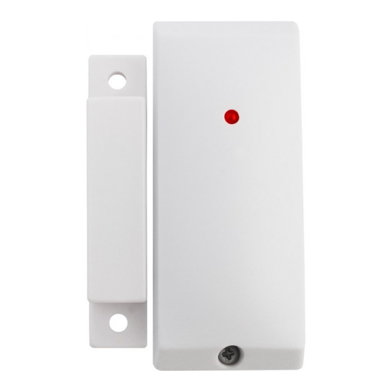
Position of the components

Above the unit is shown without the cover of the cabinet. The figure is simplified in order to easy show the position of the components.
Ondico AB is not responsible for damages that may occur due to incorrect use or if the product does not work as desired.
Introduction
- Ontech Alarmbox 9012 is a wireless device which send alarms to Ontech GSM 9020 and Ontech GSM 9030 via a short range radio at frequency 2,4 GHz. Ontech GSM 9020 and Ontech GSM 9030 will in this manual be called the master unit.
- The Alarmbox is sending an alarm message when one of the alarm inputs; NO (Normally Open) eller NC (Normally Closed) has been activated. A built-in magnetic switch is connected in parallel with the NC input. There is also a sabotage alarm, a microswitch is activated when the cabinet cover is removed.
- The Alarmbox has a built-in temperature sensor and in all messages from the unit the temperature is reported.
- Up to seven Alarmboxes can individually be connected to each main unit. One or more Ontech Relay 9010 in your Ontech system decreases the number of Alarmbox you can connect. Highest total sum of Ontech Relay 9010 and Alarmbox units is seven.
- Operating range is at least 30 meters in free field. Construction and material in houses affect the indoor operating range.
- In this manual all commands are described as SMS commands.
- Ontech also has developed apps for Android system and Iphones. Inside those apps the function is described. Search on Ontech control on Google Play or App store. Or use the QR codes below.
Google Play


App store


Idle operating mode
The Alarmbox is sending status information at start up and then every twenty minutes. This information is stored until next status update or longest 60 minutes. This means that if the Alarmbox is disconnected or stops working it will take maximum 60 minutes until it disappears from SMS messages.
Installation
- Power up you Ontech master unit.
- Deactivate the alarm function in the master unit by sending an SMS with the content:
ABCD*7*0# (ABCD is the PINCODE you have decided, see your manual for the master unit.) - Remove the cabinet from the Alarmbox by unscrew the screw and fold up the upper part.
- Set the unit ID number
- Factory setting is ID 2. If you have two or more Alarmboxes you sure want to know which one that is sending the alarm. DIP-switch 6, 7 and 8 is used to set ID number according to the table below.
| ID | Switch 6 | Switch 7 | Switch 8 |
| ID2 | OFF | OFF | ON |
| ID3 | OFF | ON | OFF |
| ID4 | OFF | ON | ON |
| ID5 | ON | OFF | OFF |
| ID6 | ON | OFF | ON |
| ID7 | ON | ON | OFF |
| ID8 | ON | ON | ON |
- Set the radio channel
- Normally you do not have to change this. If two or more Ontech system is working close to each other or if there is other types of interference another radio channel can be set. DIP-switch 2, 3, 4 and 5 is used for this purpose. They can be set in any position but most important that the setting is same on master unit and all connected Alarmboxes.
- Attach the bottom part of the cabinet with two screws at the place you want. If the magnetic switch shall be used the magnet is placed along the left side of the Alarmbox (see figure) and is centred along the side. The distance between the Alarmbox and the magnet must not be more than 3 mm.
- Connect alarm sensors
- The built-in magnetic switch
If the built-in magnetic switch shall be used at for example a door or window you must disconnect the cable jumper between the NC and GND terminal. - Alarm sensor with Normally Closed (NC) operation
The relay output from the alarm sensor is normally closed. When alarming the circuit is opened. Many PIR devices is constructed in this way.
Disconnect the cable jumper on the terminals NC and GND connectors and connect instead the two cables from the alarm sensor. - Alarm sensor with Normally Open (NO) operation
The relay output from the alarm sensor is normally open. When alarming the circuit is closed. For example level guards are constructed in this way.
Connect the cables in the NO and GND connectors on the terminal. NB, The cable jumper should NOT be removed.
- The built-in magnetic switch
- Take away the plastic insolation strap from the battery. Now the red LED is blinking a couple of times.
- Press the microswitch. The red LED shall now single blink or double blink one or two times. If it is a double blink an alarm sensor is active.
If it is single blinking or double blinking three times it means that the unit has no connection with the master unit. Control the setting of the radio channel and control/adjust the distance between the Alarmbox and the master unit. - Attach the cover of the cabinet and fix it with the screw. If you have connected an alarm sensor with wires it is necessary to make a hole for it in the lower left corner.
- Press the button on the main unit at least two times in order to acknowledge the alarm sent when the Alarmbox was powered.
- Make a status request to the main unit by sending an SMS with the content ABCD#8#. You shall receive a reply SMS with information of which units that are connected to the master unit. For interpreting the SMS, see next side.
- Activate the alarm function on the master unit by sending an SMS with the content ABCD#7*1#.
- Activate the alarm sensor and check that all telephones on the alarm list receives the Alarm SMS.
When the unit is alarming
When an alarm is activated an SMS will be sent to all mobile telephone numbers on the alarm list. The red LED is double blinking 1-3 times. Up to ten different persons can be alerted.
Below is shown an example of an alarm SMS.
| Example | Explanation |
| *Ontech9030 | Asterix (*) means the alarm function is activated. |
| Alarm: | |
| 2a, 3b | Indicates all alarms that have been activated since the last acknowledge. A a after the ID number means it is a normal alarm. A b after the ID number means it is a low battery alarm. See below. |
| Inputs: | |
| 2a | Indicates the ID of the units where the alarm sensor is still active. In this example it means the input in unit ID 2 is active and must be deactivated before you acknowledge the alarm. |
| Units: | |
| 1; 2/24; 3/22 | Indicates the IDs for the units connected to the master unit. Also the temperature at each Alarmbox is indicated. |
| Temp: | |
| 24; 24,2 | Indicates the temperature at the master unit. |
| Tstat: | |
| OFF | Indicates the status of the Thermostat function. |
Low battery warning
If the battery is low the unit will send an SMS with a b after the ID number. Replace the battery.
Acknowledge an alarm
When an alarm has been sent it has to be acknowledge before the unit can send another alarm.
First make sure that the alarm sensor is not active, that is for example shut an open door that is alarmed.
Then acknowledge by sending an SMS with the content ABCD#9#.
Status SMS
Below is shown an example of an status SMS and how it is interpreted.
| Example | Explanation |
| *Ontech9030 | Asterix (*) means the alarm function is activated. |
| Units: | |
| 1; 2/24; 3/22 | Indicates the IDs for the units connected to the master unit. Also the temperature at each Alarmbox is indicated. |
| Temp: | |
| 24; 24,2 | Indicates the temperature at the master unit. |
| Tstat: | |
| OFF | Indicates the status of the Thermostat function. |
Trouble shooting
| Symptom | Reason |
The LED is blinking all the time | Dipswitches 6, 7 and 8 are all in position OFF. Set valid ID. |
Alarm messages is sent continuously | Check that the cable jumper is connected on the NC and GND connectors on the terminal (If NC alarm sensor is connected there shall be no jumper) |
The magnetic switch is not working | Check the distanse between the cabinet and the magnet. Check that the jumber is removed. |
Compability
Ontech Alarmbox 9012 is fully compatible with master units with software revision R7 or higher.
For master units with software revision R6 or lower the temperature will not be shown.
Alarmbox units ID will not be shown in status SMS more than one minute after an update has been sent from the Alarmbox to the master unit.
See master units manual for instruction of how to check the software revision.
Tip
If there is no radio connection between the master unit and the Alarmbox, first move the units to a distance of approx. 2 meters in order to ensure that the radio works.
Also check that the DIP switch 6 on the master unit is in OFF position.
If radio contact not can be established one Ontech Relay 9010 can be used as a repeater if placed between the master unit and the Alarmbox. See the manual for the master unit for further instructions.
Technical specifications
| Short range radio | Frequncy 2,4 GHZ Power max 1 mW |
| Alarm inputs | Activated by closing or opening function. The magnetic switch is activated with the attached magnet. |
| Power | Litium battery 1/2 AA, 3 V. Will operate the unit more than two years with normal usage. |
| Temperature range | -20º C to +40ºC |
Declaration of conformity
Ondico AB, Datavägen 14A, 436 32 Askim, Sweden, hereby declares that the product Ontech Alarmbox 9012 is in conformity with the provisions of the Radio & Teleterminal directive R&TTE 1999/5/EG..


Documents / Resources
References
Download manual
Here you can download full pdf version of manual, it may contain additional safety instructions, warranty information, FCC rules, etc.
Advertisement

Need help?
Do you have a question about the Alarmbox 9012 and is the answer not in the manual?
Questions and answers