Advertisement
Quick Links
WIRING DIAGRAM
*If needed – pull down with screwdriver in slot.
Tilt upward on load side of switch to release.
Conduit Connection and Grounding Instructions - For Enclosures Not Prepared with Conduit Entry Holes
NOTES:
- Use of a UL Listed liquid-tight hub or connector fitting is required to maintain NEMA 4X, 12 or IP69K Rating.
- Use of a UL Listed hub or grounding bushing system is required for metallic grounding applications ¾" max.
- Grounding bushings are not required with non-metallic conduit.
1.
Conduit Holes – cut holes in enclosure at drill point locations only. Drill points are provided as a guide. See Fig. 6 for DS and Fig. 7 for CDS details.
Use of a standard hole saw is the preferred method.
2.
Conduit Connections
a. Metallic – secure the conduit hub onto the conduit. Then secure the conduit hub into a prepared enclosure hole using the hub nut and/or
grounding bushing inside the enclosure. Use the wiring diagram illustrated on the Wiring Instructions. Phase conductors and separate equipment
grounding conductor (if present) should be sized in accordance with N.E.C. FOLLOW GROUNDING INSTRUCTIONS BELOW
b. Non-Metallic Conduit – secure conduit to the conduit connector (hub) either before or after the conduit connector is secured into an enclosure hole
using the connector locknut. Use the wiring diagram illustrated on the Wiring Instructions. Size phase conductors and separate equipment ground to
N.E.C. FOLLOW GROUNDING INSTRUCTIONS BELOW
Grounding Instructions
IF A METALLIC CONDUIT SYSTEM IS USED TO PROVIDE THE
EQUIPMENT GROUND:
Metal conduit fittings with a ground screw on lock nut/bushing must
be utilized (not provided). Attach a properly sized ground wire (not
provided) to each ground nut/bushing screw. Secure the opposite
ends of the wire to a terminal on the green/yellow ground block
(provided on metal din rail). NOTE: Only one wire per terminal of
ground block. The "jumper" wires and ground block complete the
grounding path.
IF A SEPARATE EQUIPMENT GROUNDING CONDUCTOR IN
THE CONDUIT IS USED:
Connect the grounding conductor to the green/yellow ground block
mounted on the metal din rail. NOTE: Only one wire per terminal of
ground block.
SHORT CIRCUIT PROTECTION ACCORDING TO UL
These units are suitable for use on circuits capable of delivering not
more than 65,000 RMS Symmetrical Amperes at 600Vac Maximum.
©2020 MENNEKES ELECTRONICS INC.
SPECIFICATIONS SUBJECT TO CHANGE
DS/CDS Disconnect Switches
Wiring and Mounting Instructions
Switch
Ground
Auxiliary
Catalog Number
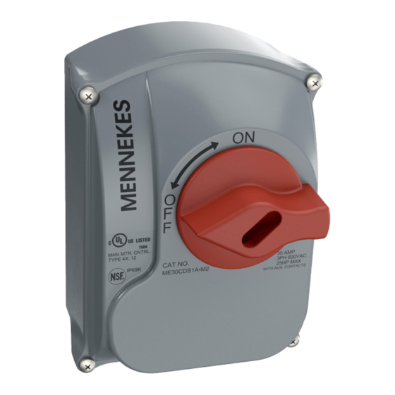
ME 30CDS1A-M2
ME 20DS1A-M2
ME 30DS1A-M2
ME 40DS1A-M2
TERMINAL SPECIFICATIONS
25 & 30Amp
Torque
#12 - 10 AWG
11 Ibs./in.
#12-10 AWG
20 Ibs./in.
#14 AWG
4 Ibs./in.
HP RATINGS
1 Ø
3 Ø
240VAC
240VAC
30A
5
10
25A
3
7.5
30A
5
10
40A
5
15
40Amp
Torque
#8 AWG
13-16 Ibs./in.
#10-8 AWG
20 Ibs./in.
#12 AWG
7 Ibs./in.
HP Ratings
3Ø
3 Ø
480VAC
600VAC
20
25
15
20
20
25
25
30
277 Fairfield Road
Fairfield, NJ 07004
973-882-8333
www.MENNEKES.com
Advertisement

Related Manuals for Mennekes ME 30CDS1A-M2

Summary of Contents for Mennekes ME 30CDS1A-M2
- Page 1 SHORT CIRCUIT PROTECTION ACCORDING TO UL These units are suitable for use on circuits capable of delivering not more than 65,000 RMS Symmetrical Amperes at 600Vac Maximum. 277 Fairfield Road Fairfield, NJ 07004 973-882-8333 ©2020 MENNEKES ELECTRONICS INC. www.MENNEKES.com SPECIFICATIONS SUBJECT TO CHANGE...
- Page 2 See Figs. 3 or 4. Prepare surface as required for hardware and mount to Flat Vertical Surface. Reinstall Cover and Tighten 4 Cover Screws to 13 in.lb max. See Fig. 5 277 Fairfield Road Fairfield, NJ 07004 973-882-8333 ©2020 MENNEKES ELECTRONICS INC. www.MENNEKES.com SPECIFICATIONS SUBJECT TO CHANGE...
Need help?
Do you have a question about the ME 30CDS1A-M2 and is the answer not in the manual?
Questions and answers