Table of Contents
Advertisement
Quick Links
Advertisement
Table of Contents

Related Manuals for MarMonix MCT-822


Summary of Contents for MarMonix MCT-822
- Page 1 Coating thickness Tester Products Code: MCT-822 User Manual WWW.MARMONIX.CO...
-
Page 2: Table Of Contents
Contents General information Application Description of the gauge Supply schedule Probe Specifications Front View Preparing 2-1 Power supply 2-2 Replacing the battery 2-3 Menu System and Basic Settings Measuring, Storage and Data processing in DIRECT and GROUP mode Calibration and measurement 4-1 General Hints for Calibration 4-2 Special hints for Calibration 4-3 General Remarks on Measurement... -
Page 3: General Information
1. General information The coating thickness gauges work either on the magnetic induction principle or on the eddy current principle, depending on the type of used. You can select the type of probe via MENU system, or it will be work automatically. -
Page 4: Application
MCT-822 gauges are suitable for laboratory, workshop and outdoor use. The probe can work on both principles, magnetic induction and on the eddy current principle. One probe only is required for coating measurement both on ferrous and non-ferrous metal substrates. -
Page 5: Description Of The Gauge
1-2 Description Of The Gauge For measurement on steel substrates, the gauge work on the magnetic induction principle, for measurement on non-ferrous metal substrates, it works on the eddy current principle. Measurement values and user information are shown on LCD, A display backlight ensures easy reading of screen data in dark conditions. -
Page 6: Probe
1-4 Probe The Probe systems are spring-mounted in the probe sleeve. This ensures safe and stable positioning of the probe and constant contact pressure. A V-groove in the sleeve of the probes facilitates reliable readings on small cylindrical parts. The hemispherical tip of the probe by the spring mounted sleeve and put on measuring object. -
Page 7: Specifications
1-5 Specifications Sensor probe Working Magnetic Eddy current principle induction principle Measuring 0~1250μm 0~1250μm range 0~49.21mils 0~49.21mils 0~850μm (±3%+1μm) 0~850μm 850μm~1250 (±3%+1μm) μm 850μm~1250μm (±5%) (±5%) 0~33.46mils (±3% + 0~33.46mils 0.039mils) (±3% + 0.039mils) Guaranteed 33.46mils~49 33.46mils~49.21mi tolerance .21mils (of reading) (±5%) (±5%) 0~5μm... -
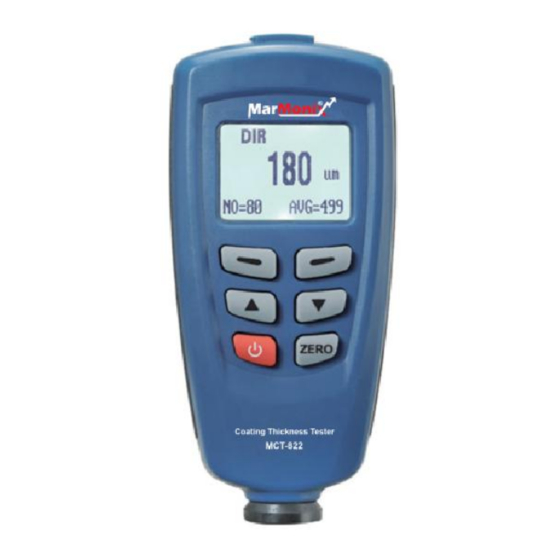
Page 8: Front View
1.968mils~33 1.968mils~33.46mi .46mils (0.01mils) (0.01mils) 33.46mils~49 33.46mils~49.21mi .21mils (0.1mils) (0.1mils) Minimum curvature radius 1.5mm Diameter of Minimum area Basic critical thickness 0.5mm 0.3mm Working temperature 0˚C~40˚C (32˚F ~ 104˚F) Working relative humidity 20%~90% Size (HxDxW): 110x50x23mm Weight: 100g 1-6 Front View 1- Probe 2- Power ON/OFF key 3- Zero Calibration key... -
Page 9: Preparing
5- Blue key for ESC/NO/BACK function in menu mode, or backlight ON/OFF In working mode 6- Main display for coating thickness 7- Measuring unit 8- NFe: indicates reading on non- ferrous metals; Fe: indicates readings on ferrous metals 9- Indicates the probe working principle: AUTO, Magnetic induction or eddy current 10- Indicates that the gauge is... -
Page 10: Replacing The Battery
No LC display: Battery missing or battery charge too low to illuminate display. Display: gauge switches off after about one second: Replace battery immediately. Note that the gauge will make faulty measurements if the voltage is very low. 2-2 Replacing The Battery Place the gauge upside down on a suitable surface. - Page 11 >> Maximum view >> Number view >>Sdev. View >Options >>Measure mode >>>Single mode >>>continuous mode >>Working mode>Limit >>>Direct>>Limit settings >>>Group 1>>>High limit >>>Group 2>>>Low limit >>>Group 3>>Delete limit >>>Group 4>Delete >>Used probe>>Current data >>>AUTO>>All data >>>Fe>>Group data >>>No Fe>Measurement view >>Unit settings>Calibration >>>um>>Enable >>>mils>>Disable...
- Page 12 >>>Maximum >>>Minimum >>>Sdev. >>Auto power off >>>Enable >>>Disable 2-3-2 Basic Settings Please refer to the MENU arrange. According to the LCD indication, Press red-bar button for OK/YES/MENU/SELECT operating functions. Press blue-bar button for ESC/NO/BACK operating functions. Press the UP/DOWN button to switch the selected item.
- Page 13 Single mode: In Single mode, readings are accompanied by a bleep. Besides, Others are same as Continuous measurement mode. 2-3-2-2 Used probe The probe can work in three modes. AUTO: The probe can automatically select the working mode. When placed on steel (magnetic substrates), it will work in magnetic induction principle.
- Page 14 Press ZERO+ simultaneously. The LC display “sure to reset”, Press red-bar button for YES, or blue-bar button for NO. The gauge will start automatically. 2-3-2-5 Backlight You can select ON/OFF in MENU system. Besides, in measuring mode, Press the blue-bar button once to switch ON/OFF backlight.
-
Page 15: Measuring, Storage And Data Processing In Direct And Group Mode
3. Measuring, storage and data processing in direct and group mode This gauge offers two operating modes: DIRECT and GROUP mode. The GROUP mode includes GRO 1~4. DIRECT mode is intended for quick occasional readings. In this mode, individual readings are logged to memory provisionally. -
Page 16: Calibration And Measurement
NOTE: in order to work in GROUP mode, e.g. to calibrate, take readings, set limit, the word “GROX” must appear on the LC display, if not, you can set measurement mode in MENU system. Press while holding the probe in the air. The gauge ... - Page 17 Two-point calibration (using a set of two calibration foils): A) Recommended for measurements on rough surfaces. B) Recommended for precise measurements on smooth surface if the thickness to be expected lies between that of the two calibration foils. 4-1-2 Storing Calibration Values If the gauge is calibrated for a particular purpose, the calibration values will be stored in memory until changed.
- Page 18 calibration of the uncoated sample must take place on a steel cylinder of similar quality with the same diameter. The calibration sample must correspond to the product sample in the following ways: Curvature radius Substrate thickness Size of measuring area ...
-
Page 19: Special Hints For Calibration
slightest impurity will affect measurement and distort readings. 4-2 Special Hints for Calibration The basic calibration stored in the gauge should only be used for measurements on even surfaces, i.e. on steel components made of conventional steel(mild steel) or on aluminum components. Firstly, you can turn into Calibration Mode via MENU (Menu->... - Page 20 <x.xμm>. Operating is different in continuous mode and single mode. See the work mode section for more details. Then, raise the probe rapidly (far from metal substrate at least 10cm) Press and hold Zero button for about 1.5 seconds, the LC display 0.0 um.
- Page 21 should be roughly equivalent to the estimated coating thickness. Repeat step 2 several times. It will get the mean value of previous calibration readings. Now take readings by placing the probe on the coating and raise it if steady. ...
- Page 22 4-2-3 Two-point Calibration Suggest that gauge is in single work made. If necessary switch to the mode as MENU system. This method requires the use of two different foils. The thicker one should be, if possible, 1.5times as thick as the thin one. ...
- Page 23 Even while a series of measurements is being taken, foil calibration can be carried as often as necessary. The old calibration will be overwritten; the ZERO calibration remains the memory until make the zero point calibration. See one-point calibration for more information. 4-2-4 Shot-blased Surfaces The physical nature of shot blased surfaces results in coating thickness reading that are too high.
-
Page 24: General Remarks On Measurement
Xeff=(Xm-Xo)±S Method B: Carry out a zero calibration of 10 readings on a shot- blased, uncoated sample. Then carry out a foil calibration on the uncoated substrate. The foil set should consist of a number of individual foils of max. 50 microns thickness each and should roughly correspond to the estimated coating thickness. -
Page 25: Limit Function
After careful calibration has been made, all subsequent measurements will lie within the guaranteed measuring tolerance. Strong magnetic fields near generators or live rails with strong currents can affect the reading. When using the statistics program for obtaining a mean value it is advisable to place the probe several times at a typical measuring spot. -
Page 26: Measurement Using Statistics
Any reading which falls outside the set tolerance limits will be registered by a warning indication: H: reading above HI limit. L: reading below LO limit. Please set the limit values using MENU system. 6. Measurement Using Statistics The gauge calculates statistics from a maximum of 80 readings (GRO1~GRO4: in total, a maximum of 400 readings can be stored). - Page 27 The sample standard deviation is a statistic that measures how “spread out” the sample is around the sample mean. The sample standard deviation increases with increasing spread out. The standard deviation of a set of numbers is the root mean square of the variance The variance of a list is the square of the standard deviation of the list, that is, the average of the squares of the deviations of the numbers in the list from their...
- Page 28 7. Delete Functions In MENU system, you can find following function: Delete current data: If you find the last measuring reading is wrong, you can delete it via this function. At the same time, the statistic will be updated. ...
- Page 29 Err4, 5, 6: reserved Err7: Thickness fault...
Need help?
Do you have a question about the MCT-822 and is the answer not in the manual?
Questions and answers