
Subscribe to Our Youtube Channel
Related Manuals for infobit iWall X Series


Summary of Contents for infobit iWall X Series
- Page 1 iWall X Video Wall Controller User Manual V1.0 www.infobitav.com info@infobitav.com...
-
Page 2: Table Of Contents
Content 1. Interface introduction ..............................3 2. Features ..................................4 3. Spec ....................................5 4. Wiring instructions ................................6 5. Install the iWall X software ............................10 6. IP setting ..................................10 7. Software connection ..............................10 8. Device activation ................................11 9. -
Page 3: Interface Introduction
1. Interface introduction Model: iWall X404 Model: iWall X408 Model: iWall X808... -
Page 4: Features
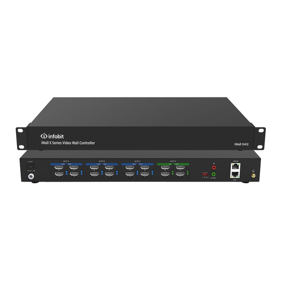
Model: iWall X412 Description 12V Power supply Dial switch IR receiver (Reserved for future) Audio Out (3.5mm) RS232 10/100M LAN HDMI output (Blue light) HDMI input (Green light) Chassis foot pad Handle Power switch 2. Features • Advanced CrossBar technology •... -
Page 5: Spec
• 4x video overlay windows per display • Video windows zoom in, zoom out, moving, overlay, roaming, resizing and switching • With 4x4, 4x8, 4x12 and 8x8 HD graphics inputs and outputs • Low power consumption • Low capture & display latency •... -
Page 6: Wiring Instructions
Seamless Switching Support Operating System FPGA pure hardware architecture, no OS Videowall and Matrix Supports both Videowall and Matrix modes OSD text Fixed OSD text* (the scrolling feature will be ready in Q3, 2023) Background picture Support Control TCP/IP, RS232 Control Software Windows PC, Android tablet Net Dimension WHD... - Page 7 2.3 The output cables to the LCD videowall must correspond to the output port sequence of the iWall X video wall controller, as shown in the figure below: *Note: the SLOT B (to LCD 1-4) is prior to the SLOT A (to LCD 5-8) for a 2x2 videowall. 2*2 videowall diagram...
- Page 8 2*4 videowall diagram 2.4 The iWall X also support LED wall. The output cables to the LED sending cards must correspond to the output port sequence of the iWall X video wall controller, same as LCD connections. 2.5 Connect the software (see Paragraph 5), after setting the screen output (see Paragraph 7), the wiring sequence of the outputs will be shown on the virtual screen area on the iWall X software;...
-
Page 10: Install The Iwall X Software
5. Install the iWall X software Copy the client software installation package iWall 3.2.7 setup to the computer, and then double-click the file and click next to complete the installation. 6. IP setting Connect the controller and the computer directly with a network cable or connect both to the same switch or router. -
Page 11: Device Activation
8. Device activation After logging in to the software, at the first time the device needs to be activated, the temporary activation code is :888888; after activation, the information can be viewed in the Settings- About menu. See below:... -
Page 12: Switching Languages
9. Switching languages Click Language to switch between Simplified Chinese, Traditional Chinese, and English as shown below: 10. LCD Videowall settings Click Settings-->Videowall, if the displays are a LCD, DLP and other standard resolution screens, you need to set the screen resolution of the iWall X output, see figure below: The Split Grid Rows and Cols means the virtual splitting grids on each LCD display, it can be used to open video windows at the right position and aspect ratio. -
Page 13: Led Wall Settings
11. LED wall settings Click Settings-->Videowall->Resolution->Custom Resolution, if the displays are a LED, you need to set the custom screen resolution of the iWall X output for the sending cards, see figure below: (The Display Rows means sending cards rows, and the Display Cols means sending cards cols.) The Split Grid Rows and Cols means the virtual splitting grids on each sending card, it can be used to open video windows at the right position and aspect ratio. -
Page 14: Source Management
12. Source management 9.1 Connect the signal source to the input ports, and the signals can be automatically identified. 9.2 There are two ways to dray the source to the videowall. 9.2.1 Double-click the signal source or drag the signal source to the specified window position, as shown in the figure below:... - Page 15 9.2.2 Select one input signal, then drag any rectangle on the right virtual videowall area. As below: 9.2.3 Click on the Layers button, choose to open the window on a single selected screen or the whole wall. As shown below:...
- Page 16 9.3 Video window management 9.3.1 Click on the right-up corner, close the current source. Click Clear All button to quickly close all the windows. As shown below:...
- Page 17 9.3.2 The source position, zoom in and zoom out can be realized by the mouse. It also can be realized by changing the parameter value of the window property by clicking the Window button; as shown in the figure below: 9.3.3 When the current layer is selected by the mouse, the current layer is placed on top;...
-
Page 18: Preset
13. Preset 10.1 After the window layers are set up, click the Save button, enter the name of the preset, and click OK, as shown in the figure below:... - Page 19 10.2 The saved presets can be viewed in the below list, as shown in the figure below: 10.3 Switch presets: double-click the name or the corresponding thumbnail to quickly switch. 10.4 Delete preset: select the preset and click Delete button.
-
Page 20: Audio Switching
10.5 Presets auto switching: select the presets you want to switch and setup the switching time interval, then click Start button to enable. 14. Audio switching Click the audio sign to mute or unmute the sound, as shown in the figure below: There is only one input signal can be enabled with audio and routed to the 3.5mm output at the rear panel of iWall X. -
Page 21: Background Image
15. Background image Click on the Others->Change Pic buttons to modify the background image and select the image in the computer. 16. Change IP address Click Settings->Network to modify the current IP, Subnet Mask, and Gateway of the videowall controller. -
Page 22: User Management And Password
17. User management and password 14.1 Click Settings->User, enter the Username and Password, click Add User or Delete User to manage. 14.2 Click Settings->Password to modify the current account password, as shown in the figure below:... -
Page 23: License
18. License 15.1 Click Settings->License to select the authorization file to import. 15.2 Click Settings->About, you can check whether the authorization information is correct, and check the software version, product model, serial number, etc. -
Page 24: Screen On/Off
19. Screen ON/Off Connect the videowall and controller with serial cable, set the Screen ON/Off in the software; set the serial port and commands. 20. Crop the input Select the input source, click the Video Crop button to cut the input images to fit the suitable aspect ratio or cut off the black edges. -
Page 25: Rename The Input
21. Rename the input Select the name of the signal source, click the Rename icon then enter a new name. As shown below:... -
Page 26: App Control
22. App control 19.1 Install the Android app on the tablet or mobile phone, make sure the WIFI connected to the tablet or mobile phone must be in the same network segment as the controller; open the APP, enter the controller's IP address, username (admin as default), and password to be empty as default, and log in. -
Page 27: Central Control
23. Central Control 21.1 Connect method. The system supports HTTP and RS232 serial port. Baud rate: 9600 Parity: none Bit: 8 Stop: 1 21.2 Package The commands sent by the central control to the device and the responses sent by the device to the central control are all encapsulated into data packets. - Page 28 number DATA Application Get videowall group One Preset: $11^ sample Get videowall group Two Preset: $12^ Get videowall group Three Preset: $13^ Get videowall group Four Preset: $14^ Equipment response: DATA A number of preset names separated by spaces (UTF8 format).
- Page 29 Preset Name "2" Code:24 33 31 32 5E Preset Name "3" Code:24 33 31 33 5E Equipment response: DATA Ok or Error 3) Gets the controller IP DATA Application sample Equipment response: DATA Controller IP. Ror instance: IP:[192.168.1.250] 4) Sets the controller IP address. DATA IP address Application...
-
Page 30: Attention
sample Equipment response: DATA Ok or Error 24. Attention To ensure the reliable use of equipment and the safety of personnel, in the installation, using, and maintenance, please comply with the following: ⚫ When the equipment is installed, make sure the controller is well grounded. ⚫...
Need help?
Do you have a question about the iWall X Series and is the answer not in the manual?
Questions and answers