
Related Manuals for SILENT KNIGHT 5495

Summary of Contents for SILENT KNIGHT 5495
- Page 1 SILENT KNIGHT 5495 Distributed Power Module Part Number 151161G, 08/03 Installation Manual...
-
Page 2: Table Of Contents
Current Requirements (Standby and Alarm) ....................8 4.3.1 Current Drawn From Host Panel ......................8 4.3.2 Current Drawn from Battery .........................8 Connecting the 5495 to a Control Panel ....................10 4.4.1 Trouble Relay .............................11 Notification Appliance Wiring ........................11 4.5.1 Class A Supervised Wiring .........................11 Class A Output Notification Circuits ....................11... - Page 3 Model 5495 Distributed Power Module Installation Manual Section 5 Connection to Silent Knight Panels ................20 Section 6 Sample Applications ........................22 Notification Power Applications ........................22 Non-Resettable Power Application ......................24 Door Holder Application ...........................25 Section 7 Troubleshooting ..........................26 LEDs ................................26 Trouble Conditions ............................27 Removing and Replacing the Control Panel ....................28...
-
Page 4: Introduction
The 5495 provides its own AC power connection, battery charging circuit, and battery connections. Used with security and fire alarm control panels, the 5495 enables you to connect and distribute power to many more devices than your panel may normally allow. -
Page 5: Ul Requirements
Model 5495 Distributed Power Module Installation Manual Section 2 UL Requirements When installed in accordance with NFPA 72 standards, the 5495 can be connected to UL Listed devices. The 5495 is also listed to meet UL Standard 864 and power limiting requirements. -
Page 6: System Overview
System Overview Section 3 System Overview CAUTION Each output circuit is rated at 3 amps. DO NOT OVERLOAD. Overloading a circuit will cause it to shut down (power limit). The circuit will automatically reset once you remove the overload condition. Terminal Descriptions and Electrical Ratings Terminal # Description... -
Page 7: Signal Input Terminals
Note: Once the inputs are driven with forward polarity to activate the outputs, the main control panel will not be able to sense trouble conditions through its notification appliance circuit connected to the 5495 input cir- cuits. Use the 5495 trouble relay when it is necessary to monitor trouble conditions and active alarm con- ditions at the same time. -
Page 8: Notification Appliance Circuit Terminals
Terminals 3 through 10 are the notification appliance circuit output terminals. Each of the four circuits are rated at 3 amps, although you can only draw a total of 6 amps from the 5495. The 5495 outputs are short-circuit protected (power limited) according to UL 864 standards. -
Page 9: Installation
Section 4 Installation Before installing the 5495, the AC input must first be wired into the building’s main electrical power through the TB1 terminals (see Figure 4-2). Shut off the electrical power to the 5495, and then complete the general installation of the 5495 using the information in this section. -
Page 10: Wire Routing
Installation Wire Routing To avoid induced noise (transfer of electrical energy from one wire to another), keep input wiring isolated from high current output and power-limited wiring. Induced noise can interfere with telephone communication or even cause false alarms. Avoid pulling a single multiconductor cable for the entire system. -
Page 11: Current Requirements (Standby And Alarm)
The total current of the 5495, plus all items powered from it, must not exceed 6 A when the panel is in alarm. Use Table 4-2 to ensure that the current does not exceed 6 A and, that the desired amount of standby is possible for the battery intended for use with the 5495. - Page 12 Current per Device Devices Current Current For each device use this formula: This column X This column = Current per number of devices. 5495 Distributed Power Module Standby: 75 mA 75 mA Alarm: 175 mA 175 mA (Current draw from battery)
-
Page 13: Connecting The 5495 To A Control Panel
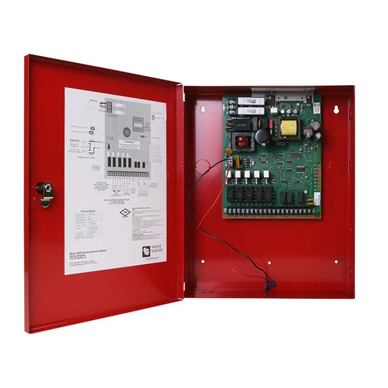
Model 5495 Distributed Power Module Installation Manual Connecting the 5495 to a Control Panel Figure 4-2 shows the general layout of the 5495 PC board. This section also provides specific wiring details for accessories. Figure 4-2 The Model 5495 PC Board Layout Consult the installation manual for specific wiring information for the control panel being used. -
Page 14: Trouble Relay
EOL supplied with the fire alarm control panel. This will cause a trouble on the fire alarm control panel when the 5495 opens its trouble contacts. Note: The N.C. contact is the contact that is closed when the 5495 has power and there are no trouble conditions. Must be connected to... -
Page 15: Class A Supervised Input Circuits
Model 5495 board. Pay close attention to the polarities when wiring a panel to the 5495 and follow these requirements: • When wiring to Terminal 18 on the 5495, you must use two separate wires. Do not loop a single wire or twist two conductors together. •... -
Page 16: Class B Supervised Input Circuits
Use an EOL resistor as shown to enable notification appliance circuit input supervision. Some panels use EOLs that have a different value from the 4.7k ohm EOL resistor used by the 5495. In this case, the EOL must be UL listed for the fire alarm control panel (not the 5495). -
Page 17: Battery Connection
Battery Connection You must use two 12 volt batteries with the 5495. Use two 12 VDC, 7 AH gel cell batteries in series, such as the, inside the 5495 cabinet. For batteries larger than 7 AH (not to exceed 33 AH)use AB-33 Accessory Battery Cabinet. -
Page 18: Selecting The Standard Input/Output Configurations
Note: The 5495 checks switches 1, 2, 3, and 6 only when powering up the 5495. If you change these switch settings, you must remove both the AC power and the battery to make the 5495 recognize the new settings. - Page 19 Temporal-coded Options With this new feature, a steady signal can produce the pattern shown above for panels not previously able to do so. Note: The 5495 can also produce temporal patterns if the inputs are non-ANSI temporal configurations. P/N 151161...
-
Page 20: Selecting Synchronized Output Configurations
Installation 4.8.2 Selecting Synchronized Output Configurations The following sections describe how to configure the 5495 as a synchronization power expander for Amseco, Faraday, Gentex, System Sensor, or Wheelock synchronized horn/ strobe appliances. Note: In order for the synchronization feature to operate properly, make sure you have set the DIP switches for the proper manufacturer. -
Page 21: Selecting Sychronized System Sensor Configurations
Model 5495 Distributed Power Module Installation Manual 4.8.2.3 Selecting Sychronized System Sensor Configurations To select the input/outputs for System Sensor synchronized appliances, set the DIP switches as shown in Figure 4-11. Figure 4-11 System Sensor Synchronized Configurations 4.8.2.4 Selecting Sychronized Wheelock Configurations To select the input/outputs for Wheelock synchronizated appliances, set the DIP switches as shown in Figure 4-12. -
Page 22: Setting The Loss Of Ac Delay
Switch 5 on the DIP switch determines how the auxiliary power operates on the 5495. The 5495 checks Switch 5 only when powering up the 5495. If you change this switch, you must remove both the AC power and the battery to force the 5495 to recognize the new switch setting. -
Page 23: Connection To Silent Knight Panels
Model 5495 Distributed Power Module Installation Manual Section 5 Connection to Silent Knight Panels The drawings in this section show you how to connect the 5495 to compatible Silent Knight panels. See panel installation manuals for more information. Figure 5-1 Connection to 5104 Fire Communicator... - Page 24 Connection to Silent Knight Panels Figure 5-3 Connection to 5204 Fire Control/Communicator Figure 5-4 Connection to 5207 Fire Control/Communicator P/N 151161...
-
Page 25: Sample Applications
Model 5495 Distributed Power Module Installation Manual Section 6 Sample Applications The drawings in this section show various 5495 configurations, including “daisy-chaining”. Notification Power Applications 5495 Local Fire Alarm Control Panel Figure 6-1 Input 1 Activates All Four Outputs 5495... - Page 26 Sample Applications Note: When multiple power supplies are used with one control unit they will not sync with each other 5495 Local Fire Alarm Control Panel 5495 Figure 6-3 One Control Activating Two 5495s 5495 Local Fire Alarm Control Panel...
-
Page 27: Non-Resettable Power Application
Figure 6-5 Each Control NAC Activates Five Output NACs Non-Resettable Power Application The 5495 provides a dedicated 3 A auxiliary power output that you can select as non-resettable (output is always on). See Section 4.8.4 for setting the auxiliary power. If you need more than 3 A, wire the inputs as shown in Figure 6-6. -
Page 28: Door Holder Application
You would have to use the equivalent of a programmable relay from a fire alarm control panel that is programmed to open under alarm conditions. See Section 4.8.4 for selecting auxiliary power options. 5495 Fire Alarm Panel ESL DHX 1224... -
Page 29: Troubleshooting
Model 5495 Distributed Power Module Installation Manual Section 7 Troubleshooting Light-emitting diodes (LEDs) indicate fault conditions. This section describes the LED states. LEDs The eight LEDs indicate a fault in one of the circuits (either NACs 1 through 4, auxiliary power, earth fault, low AC, or battery). -
Page 30: Trouble Conditions
Troubleshooting Trouble Conditions Trouble Condition What Happens Low AC Input 1 and Input 2 supervision circuits open after a 6 hour delay. (AC input voltage is low or off The green AC LED turns off as soon as low AC or loss of AC occurs (does not wait 6 hours). for 6 hours or longer.) The trouble relay is de-energized after a 6 hour delay. -
Page 31: Removing And Replacing The Control Panel
Model 5495 Distributed Power Module Installation Manual Removing and Replacing the Control Panel This section provides instruction on how to remove and replace the control panel if it is determined that the control panel needs to be repaired or replaced. -
Page 32: Ul Listed Notification Appliances
UL Listed Notification Appliances For proper operation, you must use polarized devices with a Model 7628 4.7k ohm EOL resistor on each circuit.All supervised notification applicances used with the 5495 must be polarized. Note: Not all devices can use the Sync feature, be sure to check Table A-1 to ensure the device you have chosen will work with this feature. - Page 33 Model 5495 Distributed Power Module Installation Manual Table A-1: Compatible Notification Appliances Manufacturer Model Sync Type 5386 8-Tone Horn/Strobe with Sync Strobe 5387 8-Tone Horn/Strobe with Sync Strobe 5388 8-Tone Horn/Strobe with Sync Strobe 5405 Sync Control Unit 5508 Single Gang Sync Strobe...
- Page 34 Table A-1: Compatible Notification Appliances Manufacturer Model Sync Type 130-3117C Mini Horn 130-3147C Mini Horn BLV-6 Vibrating Bell BLV-10 Vibrating Bell BLVCH Vibrating Chime H12/24-FC Horn H12/24W-FC Horn H12/24K-FC Horn HC12/24-FC Horn HC12/24W-FC Horn HC12/24K-FC Horn P2415-FC Horn/Strobe P2415W-FC Horn/Strobe P2415K-FC Horn/Strobe P241575-FC...
- Page 35 Model 5495 Distributed Power Module Installation Manual Table A-1: Compatible Notification Appliances Manufacturer Model Sync Type Horn Federal Signal VALS Horn/Strobe GX90-4 Horn GXS-4-15-1 Strobe GXS-4-1575 Strobe GX90S-4-15 Horn GX90S-4-1575 Horn HG124 Horn SHG24-1575 Horn/Strobe SHG24-15 Horn/Strobe Gentex GEC Series...
- Page 36 Table A-1: Compatible Notification Appliances Manufacturer Model Sync Type System Sensor PS2475ADA Mini-Horn/Strobe (Cont.) Sync. Module MDLW Sync. Module 46T-G4-24-R Bell 46T-G6-24-R Bell 46T-G10-24-R Bell 46T-G6-24-WS-24-HF-R Strobe/Bell 46T-G10-24-WS-24-HF-R Strobe/Bell 46T-G6-24-WH-24-HF-R Strobe/Bell 46T-G10-24-WH-24-HF-R Strobe/Bell 7001T-12\24-W-FR Strobe Horn 7002T-12\24-W-FR Strobe Horn AES-DL1-R Multitone Horn AES-EL1-R Multitone Horn...
- Page 37 Model 5495 Distributed Power Module Installation Manual Table A-1: Compatible Notification Appliances Manufacturer Model Sync Type CF-BF1-R Chime CH-CF1 Chime CH-CF1-R Chime CH-CF1-W Chime CH-DF1 Chime CH-DF1-R Chime CH-BF1-WS-24-HF-R Strobe Chime CH-CF1-LS-24 Strobe Chime CH-CF1-MS-24 Strobe Chime CH-CF1-IS-24 Strobe Chime...
- Page 38 Table A-1: Compatible Notification Appliances Manufacturer Model Sync Type IS1-24-VFR Remote Strobe IS3-24-VFR Remote Strobe ISP-24-HFR Remote Strobe LS-24-VFR Remote Strobe LS1-24-VFR Remote Strobe LS3-24-VFR Remote Strobe LSP-24-HFR Remote Strobe LSM-24-VFR Remote Strobe LS1M-24-VFR Remote Strobe LS3M-24-VFR Remote Strobe LSPM-24-VFR Remote Strobe MS-24-VFR Remote Strobe...
- Page 39 Model 5495 Distributed Power Module Installation Manual Table A-1: Compatible Notification Appliances Manufacturer Model Sync Type NS-24MCM-FR Horn Strobes NS-24MCW-FW Horn Strobes NS-2415W-FR Horn Strobes NS-241575W-FR Horn Strobes NS-2430W-FR Horn Strobes NS-2475W-FR Horn Strobes NS-24110W-FR Horn Strobes NS4-24MCW-FR Horn Strobes...
- Page 40 Table A-1: Compatible Notification Appliances Manufacturer Model Sync Type SM-12/24-R Sync Module SR-2415-VFR Sync Strobe SRP-2415-HFR Sync Strobe SR-241575-VFR Sync Strobe SRP-241575-VFR Sync Strobe SR-2475-VFR Sync Strobe SR-2475-HFR Sync Strobe Wheelock SR-24110-HFR Sync Strobe (Cont.) SRP-24110-HFR Sync Strobe V7001T-12\24-W-FR Strobe Horn WM3T-24-FR Remote Strobe WM3T-24-VFR...
- Page 41 Model 5495 Distributed Power Module Installation Manual P/N 151161...
- Page 42 Repair and RA Procedure • All products that are returned to Silent Knight for credit or repair require a RA (Return Authorization) number. Call Silent Knight Customer Service at 800-446-6444 or 763-493- 6435 between 8:00 A.M. and 4:45 P.M. CST, Monday through Friday to obtain a return authorization number.
- Page 43 Upon return of the defective product, Silent Knight will at its sole discretion, either repair or replace, at no cost, such goods as may be of defective material or workmanship. Customers outside the United States are to return products to their distributor for repair.
- Page 44 7550 Meridian Circle Maple Grove, MN 55369-4927 763-493-6455 1-800-328-0103 Fax: 763-493-6475 © 2003 Silent Knight Part Number 151161G, 08/03...
Need help?
Do you have a question about the 5495 and is the answer not in the manual?
Questions and answers