Advertisement
Quick Links
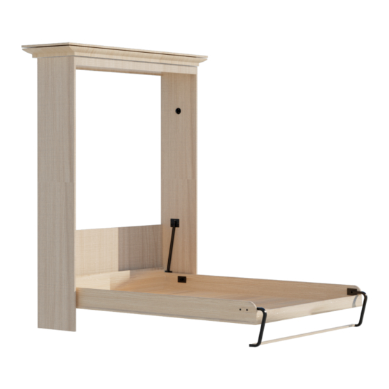
Murphy Bed Building Instruction Manual
(Queen Vertical)
Note: If you encounter any problems with the installation, missing
or replacement parts, please Contact ROOMTEC.
Please also tell us your "ORDER ID," we will solve the issue for
you as soon as possible.
Customer Service: (800)209-3199 (MON -FRI 9:00am-5:00pm
Eastern Time) or hello@room-tec.com
Advertisement

Related Manuals for RoomTec Murphy Bed Building Queen Vertical


Summary of Contents for RoomTec Murphy Bed Building Queen Vertical
- Page 1 Murphy Bed Building Instruction Manual (Queen Vertical) Note: If you encounter any problems with the installation, missing or replacement parts, please Contact ROOMTEC. Please also tell us your “ORDER ID,” we will solve the issue for you as soon as possible.
-
Page 2: Tools Needed
PLEASE INSPECT YOUR BOX CONTENTS TO ENSURE YOU HAVE RECEIVED ALL COMPONENTS. Warning!This bed contains stored mechanical energy ,which can cause serious injury if improperly handled. Your bed must be securely anchored to the wall! Read instructions and watch the video thoroughly before assembly and disassembly! Online Video: bit.ly/deluxeverticalvideo... - Page 3 Two (2) Metal Pivoting Legs Four (4) Leg Support Rail SCREWS Four (4) Black SCREWS Four (4) "T" Nuts with machine SCREWS Two (2) pair of METAL PIVOTS Four (4) BALL STUD PLATES with two (2) plastic spacers with twelve (12) black SCREWS Two (2) "E"...
- Page 4 OUT-TO-OUT DIMENSIONS OF VERTICAL STYLE MURPHY BED CABINET OUTSIDE-EDGE TO OUTSIDE-EDGE FINISHED VERTICAL BED CABINET DIMENSIONS Finished bed cabinet 15-7/8 Depth Projection into room From wall Finished bed cabinet 65-7/8 Width Note: Your mattress dimensions must not exceed 60"x 80". Mattress thickness CANNOT exceed 12"...
- Page 5 Components of finished murphy bed A. Inner Wood Bed Frame B. Side Rails C. Foot Rail D. Head Rail E. Bed Face Panels F. Bed Headboard G. Bed Cabinet Verticals H. Bed Header I. Leg Support Rail J. 1/4" Plywood Mattress Support - 04 -...
- Page 6 QUEEN SIZE DELUXE KIT VERTICAL BED PLYWOOD CUTTING GUIDE Requires: 4 sheets of 3/4" x 4' x 8' and 2 sheets of 1/4" x 4’x 8’ NOTE:Refer to page 6 for the cutting dimensions. G. Cabinet Verticals H. Rear Rail E.
- Page 7 QUEEN SIZE DELUXE KIT VERTICAL BED WITH 3/4" PLYWOOD FACE PANEL BILL OF MATERIALS / CUT SHEET Note: Do not substitute other materials. _check off as completed. _A. INNER WOOD BED FRAME:*To be constructed of solid wood: poplar, clear pine, maple, etc.* FRAME STRUTS: *SOLID WOOD* 3/4"...
- Page 8 PART A.INNER WOOD BED FRAME Frame sides Frame struts Ends are flush Glue Step 1: Construction of five (5) frame struts. Run a bead of wood glue along inside edge. Making sure ends are flush,drill pilot holes approximately 8" apart and nail with 1-1/2" finish nails, or you can use #8×1-1/2"...
- Page 9 PART B. SIDE RAILS: (MUST BE MADE OF PLYWOOD) Why?..This is where the stress takes place. Plywood is stronger than solid wood. YES EVEN SOLID OAK…… PART C. FOOT RAIL PART D. HEAD RAIL See pages 9,10,11,12 for placement of pivotings leg bracket &...
- Page 10 HARDWARE PLACEMENT FOR B.SIDE RAILS Step 5: See pages 13,14,15,16 for Placement of female pivot and lower ball stud plates. Step 4: See pages 10,11,12 for placement of pivotings. leg bracket & templates. 0.375 Step 6:PART I. LEG SUPPORT RAIL SEE PAGE 6 FOR CUTTING DIMENSIONS.
- Page 11 Note: Align the paper template with the edge of the B. side rail according to the orientation shown in the figure below. 8 Template Template 7 Template Note: Please place the template on the inside of the side rail, and then drill according to the Template instructions on the template NOTE: Be sure to follow the instructions on the template exactly for...
- Page 12 B.RIGHT SIDE RAIL. Step 7: Leg placement From the top of the side rail measure down 2-1/2"and from the front measure in 3-1/8". Drill a 5/8" diameter hole 1/2" deep. Step 8: Place the leg pivot into the 5/8" hole. With the pivot plate parallel to the top &...
- Page 13 B.LEFT SIDE RAIL. Step 9: Leg placement From the top of the side rail measure down 2-1/2"and from the front measure in 3-1/8". Drill a 5/8" diameter hole 1/2" deep. Step 10: Place the leg pivot into the 5/8" hole. With the pivot plate parallel to the top &...
- Page 14 This page pertains to the orientation and mounting positions of the lower ball stud plates and female pivots, USE WITH PAGES 14,15,&16 BALL STUD PLACEMENT To help you achieve this position, cut a piece of wood 5/16" thick and LOWER BALL STUD PLATE: place it under the BALL ONLY Mount to the outside of the while you screw the plate in place.
- Page 15 Step 11: Mounting the lower ball stud plate to the outside of the SIDE RAIL PARTS B. 5/16 7- 1/2 5/16 Screw two (2) black 1- 7/8 screws through these two (2) holes Drill 1 diameter PIVOT HOLE OVERHANG Mark and drill a 1/4" diameter hole through the SIDE RAIL.
- Page 16 Step 12: Mounting the lower ball stud plate to the outside of the side rail PARTS B. 5/16 7 1/2 5/16 Screw two (2) black screws 1- 7/8 through these two (2) holes Drill 1 diameter PIVOT HOLE OVERHANG Mark and drill a 1/4" diameter hole through the SIDE RAIL.
- Page 17 Step 13: Mounting female pivot plates Mount female pivot plate to inside of right and left side rails as shown. Press pivot into pivot hole.Using eight (8) silver screws provided, screw plate flush to rail. - 16 -...
- Page 18 Step 14: Mounting the foot rail PART C and head rail D. Drill 1/8" pilot hole 1-1/4" deep through the inner wood bed frame into the foot rail. Drive #8x 1-1/4" screws flush. repeat on part D Head Rail. Flush Note: Make sure the ends and bottoms of the foot rail are flush with the inner wood bed frame.
- Page 19 Step 17: Step 18: Note: For a finished look, apply wood veneer or Turn face panels over. On back side, mark melamine edge tape to all edges marked a 1/4" line the full length of the panel along finished long edge. Pick the best side of part E Face Panel for the front of the bed.
- Page 20 Step 20: Lay bed face panel with good side DOWN, and place assembled bed frame on top of bed face panel. Check to make sure the 1/4" lines are visible on both sides of the assembled bed frame. Tip: As a guide for the application of the adhesive, mark a pencil line on the face panels PARTS E around the inner wood bed frame.
- Page 21 Face panel and foot rail MUST be flush at this end. The face panel MUST extend 1/4'' past edge of frame on long sides. Step 21: Make sure face panel and foot rail are flush and that face panel extends 1/4" past edge of wood bed frame on long sides.
- Page 22 Placement of cabinet handles for optimal leverage should be between 5' and 6' on face panel PART E. - 21 -...
- Page 23 Note: Align the paper template with the edge of the G.bed cabinet vertical according to the orientation shown in the figure below. 1 Template 2 Template G.BED G.BED CABINET CABINET VERTICAL VERTICAL S (LEFT) S (RIGHT) 3 Template 4 Template - 22 -...
- Page 24 PART G : BED CABINET VERTICALS (LEFT) Measurements For QUEEN Vertical (Upright) ONLY Using 3/4" PLYWOOD Face Panel. Step 22: BED STOP: Drill two (2) holes 5/16" diameter x 1/2" deep. Insert the bed stop pin into hole and attach with two (2) black screws.
- Page 25 PART G:BED CABINET VERTICALS (RIGHT) Measurements For QUEEN Vertical (Upright) ONLY Using 3/4" PLYWOOD Face Panel. Step 25: BED STOP: Drill two (2) holes 5/16" diameter x 1/2" deep. Insert the bed stop pin into hole and attach with two (2) black screws.
- Page 26 PART F: BED HEADBOARD Step 28: Note: For a finished look,apply wood veneer or melamine edge tape to all edges marked - 25 -...
- Page 27 PART H:BED HEADER COMPONENTS Note: For a finished look, apply wood veneer or melamine edge tape to all edges marked - 26 -...
- Page 28 Step 29: Using #8 x 2" screws,glue and screw rear rail to header board,maintaining a 1/2" lip on the underside of the header board. Note: Rear rail must be glued and screwed to header board. Side view Step 30: Using 2" finish nails, glue and nail front rail to header board, maintaining a 1/2"...
- Page 29 AFTER-SALES SERVICE CARD We sincerely thank you for trusting our service and our products, and may this product add enrichment to your home. We guarantee that the product has undergone strict quality inspection and meticulous packaging. If you encounter any issue regarding either shipping or the product, please feel free to contact us at any time.
Need help?
Do you have a question about the Murphy Bed Building Queen Vertical and is the answer not in the manual?
Questions and answers
This bed gets anchored to the wall. Does it need to be anchored to the floor as well?
The manual states that the bed must be securely anchored to the wall but does not mention anchoring it to the floor. Therefore, it does not need to be anchored to the floor.
This answer is automatically generated