Table of Contents
Advertisement
Quick Links
Advertisement
Table of Contents
Troubleshooting

Related Manuals for Faulhaber MC 3603 S


Summary of Contents for Faulhaber MC 3603 S
- Page 1 Technical Manual MC 3603 S WE CREATE MOTION...
- Page 2 Dr. Fritz Faulhaber GmbH & Co. KG. This document has been prepared with care. Dr. Fritz Faulhaber GmbH & Co. KG cannot accept any liability for any errors in this document or for the consequences of such errors. Equally, no liability can be accepted for direct or consequential damages resulting from improper use of the equipment.
-
Page 3: Table Of Contents
Connection option 6890 for DC-motors with encoders IE3, IE3 L ................. 26 3.3.2 MC 3603 S ET ..................30 3.3.2.1 Connector pin assignment of MC 3603 S ET extended version ..................32 3.3.2.2 Connection option 6889 for DC-motors with encoders IE2, IEH2, IEH3, IEH3 L............39 3.3.2.3... - Page 4 Content 4.3.4 Shielding ....................63 4.3.4.1 Establishing the shield connection ........64 4.3.4.2 Establishing shield connection with cable lug ..... 65 4.3.5 Sensor and encoder interfaces ............. 66 4.3.5.1 Analog sensors and analog Hall sensors ......67 4.3.5.2 Incremental encoders / Digital Hall sensors / Digital sensors 67 4.3.5.3 Encoders with absolute interface .........
-
Page 5: About This Document
About this document Validity of this document This document describes the installation and use of the FAULHABER MC 3603 S series. This document is intended for use by trained experts authorised to perform installation and electrical connection of the product. -
Page 6: List Of Abbreviations
About this document List of abbreviations Abbreviation Meaning Alternating Current AnIn Analog input AGND Analog Ground CAN_L CAN-Low CAN_H CAN-High Clock Chip Select DigIn Digital input DigOut Digital output Electronics Filter Conformity Electronics Filter Motor Electronics Filter Supply Electromagnetic compatibility Electrostatic discharge EtherCAT (Ethernet for Control Automation Technology) Ground... -
Page 7: Symbols And Designations
About this document Symbols and designations DANGER DANGER Danger with high level of risk: if not avoided, death or serious injury will result. Measures for avoidance WARNING WARNING Danger with medium level of risk: if not avoided, death or serious injury may result. ... -
Page 8: Safety
Safety Safety Intended use The Motion Controllers described here are designed for use for control and positioning tasks for the following motors: DC-motors Linear DC-Servomotors Brushless DC-motors The Motion Controllers described here are designed for use as slaves for control and posi- tioning tasks for the following motors: ... -
Page 9: Safety Instructions
Safety Safety instructions In addition to the safety risks described in this technical manual, machine-specific dangers could arise that cannot be foreseen by the manufacturer of the Motion Controller (e.g., risk of injury from driven components). The manufacturer of the machine in which the Motion Controller is installed must perform a risk analysis in accordance with the regulations appli- cable to the machine and inform the end user of the residual risks. -
Page 10: Heat Development
Safety Soiling, foreign bodies, humidity and mechanical influences can damage the electronics. Keep foreign objects away from the electronics. Install the Motion Controller in a housing that protects it from mechanical influences and is adapted to the ambient conditions (protection class determination). Installation and connection work while supply voltage is applied at the device can damage the electronics. -
Page 11: Ec Directives On Product Safety
Safety EC directives on product safety The following EC directives on product safety must be observed. If the Motion Controller is being used outside the EU, international, national and regional directives must be also observed. Machinery Directive (2006/42/EC) The controllers with attached motor described in this technical manual may be drive sys- tems according to the Machinery Directive. -
Page 12: Product Description
DIN rail. The output stages are exchangeable and are matched to the various sizes and types of motors, i.e. DC, BL and LM motors from 13 – 42 mm, as listed in the FAULHABER product portfolio. -
Page 13: Product Information
MC 3603 S ET with connection option 6889 for DC-motors with encoders IE2, IEH2, IEH3, IEH3L, see chap. 3.3.2.2, p. 39 MC 3603 S ET with connection option 6890 for DC-motors with encoders IE3, IE3 L, see chap. 3.3.2.3, p. 44 1st edition, 20.04.2021... -
Page 14: Mc 3603 S Rs/Co
Product description 3.3.1 MC 3603 S RS/CO The MC 3603 S RS/CO Motion Controllers can be addressed via either the RS232 interface or via the CANopen interface. The USB interface is available in all devices. Status Fig. 3: MC 3603 S RS/CO standard version 1st edition, 20.04.2021... -
Page 15: Mc 3603 S Rs/Co Connector Pin Assignment
Red (continuously flashing): The drive has switched to a fault state. The output stage will be switched off or has already been switched off. Red (error code): Booting has failed. Please contact FAULHABER Support. 3.3.1.1 MC 3603 S RS/CO connector pin assignment Motor connection (M1) Tab. - Page 16 Ground connection COS(+) Cosine signal SIN(+) Sine signal n.c. – Only in combination with sin/cos sensors on FAULHABER LM motors or BX4 motors in sin/cos special version. Tab. 9: Electrical data of the sensor connection (M2) Designation Value Sensor power supply <100 mA...
- Page 17 Product description Encoder connection (M3) The pin assignment of the encoder connector varies depending on the encoder type. Incremental encoder with or without line driver Absolute encoder with or without line driver. The encoder model is selected in the configuration of the Motion Controller during com- missioning.
- Page 18 Product description Tab. 13: Electrical data for incremental encoder without line driver (M3) Designation Value Power supply for incremental encoder <100 mA Connection of the incremental <5 V encoder <2 MHz 5 kΩ Tab. 14: Pin assignment for absolute encoder with line driver (M3) Designation Meaning Power supply for absolute encoder...
- Page 19 Product description Tab. 17: Electrical data for absolute encoder without line driver (M3) Designation Value Absolute encoder power supply <100 mA Connection Chip Select Connection data <5 V 5 kΩ Connection clock 1 MHz USB (X1) Tab. 18: USB port Designation Meaning USB communication (USB micro B)
- Page 20 Product description I/O connection (X3) Tab. 21: Pin assignment of the I/O connection (X3) Designation Meaning Power supply for external consumer loads 9 11 13 Ground connection DigOut 1 Digital output (open collector) DigOut 2 Digital output (open collector) DigIn 1 Digital input DigIn 2 Digital input...
-
Page 21: Connection Option 6889 For Dc-Motors With Encoders Ie2, Ieh2, Ieh3, Ieh3 L
Connection option 6889 for DC-motors with encoders IE2, IEH2, IEH3, IEH3 L Status M3/1 M3/3 M3/2 Fig. 4: MC 3603 S RS/CO with connection option 6889 for DC-motors with encoders IE2, IEH2, IEH3, IEH3 L 1st edition, 20.04.2021 7000.05072, 1st edition, 20.04.20217000.05072... - Page 22 Product description Tab. 23: Connector overview and DIP switch Designation Function M1 (motor) Connection of the motor phases M3/1 (encoder) Connection of an IE2, IEH2 incremental encoder M3/2 (encoder) Connection of an IEH3 incremental encoder M3/3 (encoder) Connection of an IEH3 L incremental encoder X1 (USB) USB interface connection X2 (COM)
- Page 23 Product description Tab. 27: Electrical data of the DC motor connection (M1) Designation Value Motor power supply 0...U Max. 9 A 100 kHz Motor and IE2, IEH2 encoder connection (M3/1) Tab. 28: Pin assignment of the motor and IE2, IEH2 encoder connection (M3/1) Designation Meaning Motor –...
- Page 24 Product description Motor and IEH3 encoder connection (M3/2) Tab. 30: Pin assignment of the motor and IEH3 encoder connection (M3/2) Designation Meaning – n.c. Motor – Connection of the motor, negative pole Motor + Connection of motor, positive pole Ground connection Power supply for incremental encoder Channel B Encoder channel B...
- Page 25 Product description Motor and IEH3L encoder connection (M3/3) Tab. 32: Pin assignment of the motor and IEH3L encoder connection (M3/3) Designation Meaning Motor – Connection of the motor, negative pole Power supply for incremental encoder Ground connection Motor + Connection of motor, positive pole Channel A Encoder channel A (logically inverted sig- nal)
-
Page 26: Connection Option 6890 For Dc-Motors With Encoders Ie3, Ie3 L
Product description 3.3.1.3 Connection option 6890 for DC-motors with encoders IE3, IE3 L Status M3/1 M3/2 Fig. 5: MC 3603 S RS/CO with connection option 6890 for DC-motors with encoders IE3, IE3 L 1st edition, 20.04.2021 7000.05072, 1st edition, 20.04.20217000.05072... - Page 27 Product description Tab. 34: Connector overview on motor side and DIP switch Designation Function M1 (motor) Connection of the motor phases M3/1 (encoder) Connection of an IE3 incremental encoder M3/2 (encoder) Connection of an IE3 L incremental encoder X1 (USB) USB interface connection X2 (COM) CAN/RS232 interface connection...
- Page 28 Product description Tab. 38: Electrical data of the DC motor connection (M1) Designation Value Motor power supply 0...U Max. 9 A 100 kHz IE3 encoder connection (M3/1) Tab. 39: Pin assignment of the IE3 encoder connection (M3/1) Designation Meaning – n.c.
- Page 29 Product description IE3L encoder connection (M3/2) Tab. 41: Pin assignment of the IE3L encoder connection (M3/2) Designation Meaning – n.c. Power supply for incremental encoder Ground connection – n.c. Channel A Encoder channel A (logically inverted sig- nal) Channel A Encoder channel A Channel B Encoder channel B (logically inverted sig-...
-
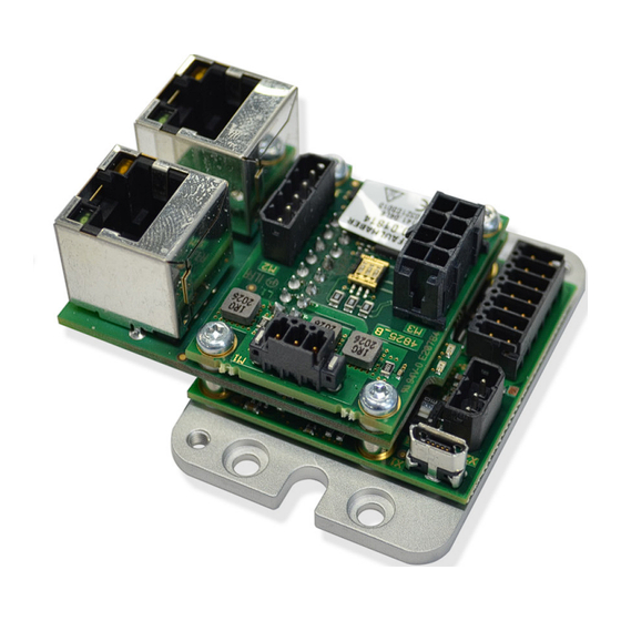
Page 30: Mc 3603 S Et
3.3.2 MC 3603 S ET Motion Controller MC 3603 S ET offers a direct EtherCAT interface for networking. On con- nector X2, only the RS232 interface is supported by the firmware. The USB interface is avail- able in all devices. - Page 31 Voltage supply of the controller and motor, inputs or outputs for external circuits IN/OUT Connection of the EtherCAT communication S1 (DIP switch The firmware of the MC 3603 S ET Motion Controller supports only the RS232 interface on COM) X2. DIP switch S1 must not be actuated. S2 (DIP switch...
-
Page 32: Connector Pin Assignment Of Mc 3603 S Et Extended Version
Product description 3.3.2.1 Connector pin assignment of MC 3603 S ET extended version Motor connection (M1) Tab. 45: Pin assignment of the BL motor connection (M1) Designation Meaning Motor A Connection of motor, phase A Motor B Connection of motor, phase B... - Page 33 COS(+) Cosine signal SIN(+) Sine signal n.c. – Only in combination with sin/cos sensors on FAULHABER LM motors or BX4 motors in sin/cos special version. Tab. 51: Electrical data of the sensor connection (M2) Designation Value Sensor power supply <100 mA Sensor connection <5 V...
- Page 34 Product description Encoder connection (M3) The pin assignment of the encoder connector varies depending on the encoder type. Incremental encoder with or without line driver Absolute encoder with or without line driver. The encoder model is selected in the configuration of the Motion Controller during com- missioning.
- Page 35 Product description Tab. 55: Electrical data for incremental encoder without line driver (M3) Designation Value Power supply for incremental encoder <100 mA Connection of the incremental <5 V encoder <2 MHz 5 kΩ Tab. 56: Pin assignment for incremental encoder without line driver (M3) Designation Meaning Power supply for incremental encoder...
- Page 36 Product description Tab. 59: Electrical data for absolute encoder without line driver (M3) Designation Value Absolute encoder power supply <100 mA Connection Chip Select Connection data <5 V 5 kΩ Connection clock 1 MHz USB (X1) Tab. 60: USB port Designation Meaning USB communication (USB micro B)
- Page 37 Product description I/O connection (X3) Tab. 62: Pin assignment of the I/O connection (X3) Designation Meaning Power supply for external consumer loads 9 11 13 Ground connection DigOut 1 Digital output (open collector) DigOut 2 Digital output (open collector) DigIn 1 Digital input DigIn 2 Digital input...
- Page 38 Product description EtherCAT port (IN/OUT) Tab. 64: Pin assignment EtherCAT (IN/OUT) Designation Meaning IN/OUT EtherCAT communication Pin 1: TxD+ Transmission Data + Pin 2: TxD– Transmission Data – Pin 3: RxD+ Receiver Data + Pin 6: RxD– Receiver Data – 1st edition, 20.04.2021 7000.05072, 1st edition, 20.04.20217000.05072...
-
Page 39: Connection Option 6889 For Dc-Motors With Encoders Ie2, Ieh2, Ieh3, Ieh3 L
Connection option 6889 for DC-motors with encoders IE2, IEH2, IEH3, IEH3 L Status ERR RUN M3/1 M3/3 M3/2 Fig. 7: MC 3603 S ET with connection option 6889 for DC-motors with encoders IE2, IEH2, IEH3, IEH3 L 1st edition, 20.04.2021 7000.05072, 1st edition, 20.04.20217000.05072... - Page 40 Voltage supply of the controller and motor, inputs or outputs for external circuits IN/OUT Connection of the EtherCAT communication S1 (DIP switch The firmware of the MC 3603 S ET Motion Controller supports only the RS232 interface on COM) X2. DIP switch S1 must not be actuated. S2 (DIP switch...
- Page 41 Product description Tab. 69: Electrical data of the DC motor connection (M1) Designation Value Motor power supply 0...U Max. 9 A 100 kHz Motor and IE2, IEH2 encoder connection (M3/1) Tab. 70: Pin assignment of the motor and IE2, IEH2 encoder connection (M3/1) Designation Meaning Motor –...
- Page 42 Product description Motor and IEH3 encoder connection (M3/2) Tab. 72: Pin assignment of the motor and IEH3 encoder connection (M3/2) Designation Meaning – n.c. Motor – Connection of the motor, negative pole Motor + Connection of motor, positive pole Ground connection Power supply for incremental encoder Channel B Encoder channel B...
- Page 43 Product description Motor and IEH3L encoder connection (M3/3) Tab. 74: Pin assignment of the motor and IEH3L encoder connection (M3/3) Designation Meaning Motor – Connection of the motor, negative pole Power supply for incremental encoder Ground connection Motor + Connection of motor, positive pole Channel A Encoder channel A (logically inverted sig- nal)
-
Page 44: Connection Option 6890 For Dc-Motors With Encoders Ie3, Ie3 L
3.3.2.3 Connection option 6890 for DC-motors with encoders IE3, IE3 L Status ERR RUN M3/1 M3/2 Fig. 8: MC 3603 S ET with connection option 6890 for DC-motors with encoders IE3, IE3 L 1st edition, 20.04.2021 7000.05072, 1st edition, 20.04.20217000.05072... - Page 45 Voltage supply of the controller and motor, inputs or outputs for external circuits IN/OUT Connection of the EtherCAT communication S1 (DIP switch The firmware of the MC 3603 S ET Motion Controller supports only the RS232 interface on COM) X2. DIP switch S1 must not be actuated. S2 (DIP switch...
- Page 46 Product description Tab. 80: Electrical data of the DC motor connection (M1) Designation Value Motor power supply 0...U Max. 9 A 100 kHz IE3 encoder connection (M3/1) Tab. 81: Pin assignment of the IE3 encoder connection (M3/1) Designation Meaning – n.c.
- Page 47 Product description IE3L encoder connection (M3/2) Tab. 83: Pin assignment of the IE3L encoder connection (M3/2) Designation Meaning – n.c. Power supply for incremental encoder Ground connection – n.c. Channel A Encoder channel A (logically inverted sig- nal) Channel A Encoder channel A Channel B Encoder channel B (logically inverted sig-...
-
Page 48: Installation
Installation Installation Only trained experts and instructed persons with knowledge of the following fields may install and commission the Motion Controller: Automation technology Standards and regulations (such as the EMC Directive) Low Voltage Directive Machinery Directive ... -
Page 49: Attachment Via The Side Plates
Installation DANGER DANGER The function of the Motion Controller is not ensured if the visual inspection criteria are not satisfied. If the function is not ensured, the drive may start unexpectedly. Depending on the use of the Motion Controller, this can lead to severe or fatal injury. Do not start up the Motion Controller. -
Page 50: Installation With Top-Hat Rail Clips
Installation 4.1.3 Installation with top-hat rail clips Recommended installation materials: ® Preferred: Top-hat rail mounting brackets from LogiLink , item no. MP0049 Mounting foot, WAGO item number 209-188 M 0049 209-188 Fig. 10: Installation with top-hat rail clips (examples) Motion Controller Clamping pin (WAGO, 209-188) ®... -
Page 51: Electrical Connection
A short-term voltage peak during braking can damage the power supply or other con- nected devices. For applications with high load inertia, the FAULHABER Braking Chopper of the BC 5004 series can be used to limit overvoltages and thereby protect the power supply. For more detailed information see the data sheet for the Braking Chopper. -
Page 52: Drive Connections
Installation 4.2.2 Drive connections The maximum length of the cable between the Motion Controller and motor depends on the sensor system used and the electrical and magnetic fields in the environment. Tab. 85: Guide values for the cable length Encoder type Unshielded length Shielded length Digital Hall sensors... -
Page 53: Connection Of The Power Supply
Installation 4.2.3 Connection of the power supply Discrete inputs and outputs (for instance for discrete set-point specification or for con- nection of limit switches and reference switches) Communication connections Make sure that the connection cables on the connection side are not longer than 3 m. ... -
Page 54: I/O Circuit Diagrams
Installation 4.2.4 I/O circuit diagrams AGND – AnIn Fig. 13: Analog input circuit diagram (internal) So that the voltage drop on the supply side does not affect the speed specification value, connect the analog input ground (AGND) to the power supply ground (GND). The analog inputs are executed as differential inputs. -
Page 55: External Circuit Diagrams
Installation DigOut DigOut Fig. 15: Digital output circuit diagram (internal) The digital output has the following properties: Open collector switch to ground Monitored output current (switch opens in the event of an error) A digital output can be assigned to an error output. It can be freely programmed. 4.2.5 External circuit diagrams Bipolar analog set-point specification via potentiometer... - Page 56 Installation Analog set-point specification via potentiometer with internally set offset and scaling Motion Controller AnIn AGND – Interface Fig. 17: Analog set-point specification via potentiometer with internally set offset and scaling Connection of reference and limit switches Motion Controller DigIn X DigIn Y Limit Switch Interface...
- Page 57 Installation Connection of an external incremental encoder 2,7k DigIn1 DigIn2 Quadrature Encoder Counter DigIn3 Index Index Interface Fig. 19: Connection of an external incremental encoder Depending on the type of encoder it may be necessary to use additional pull-up resis- tors.
- Page 58 Installation Connection to the CANopen network Node 1 Node n CAN_H CAN Bus Line CAN_L Fig. 21: Connection to the CANopen network If the CAN wiring is not laid in a straight line it may be necessary to individually opti- mize the amount and location of the terminating resistors.
-
Page 59: Electromagnetic Compatibility (Emc)
Installation Electromagnetic compatibility (EMC) Follow the instructions in the following chapters to perform an EMC-compliant installa- tion. WARNING WARNING The Motion Controller can cause high-frequency interference which can affect the function of electronic implants and other electronic devices. Take appropriate interference suppression measures, particularly during use in residen- tial environments. - Page 60 Installation AC-mains system Power adapter Filter Control Filter Motor Line Motor filter filter filter PELV Fig. 23: Interference sources in an AC-mains system Mains impedance of mains transformer – power supply connection Common-mode impedance of electronics on DC side Common-mode impedance of electronics on AC side – power supply connection Impedance of motor housing –...
-
Page 61: Functional Earthing
Installation Problem solutions The interference may vary depending on load and installation. Solution Mode of action Benefits Disadvantages Removes RF common- Does not remove all inter- 3-phase common-mode Removes common-mode mode interference ference choke / ferrite ring around interference of the ... -
Page 62: Cable Routing
Installation 4.3.3 Cable routing WARNING WARNING Voltages >25 V AC are generated and transmitted in the drive system. Set up the wiring of the drive system in a touch-proof manner. Only operate the drive system on an SELV or PELV power supply network. The cable routing depends on various factors, such as: Is the cable shielded, twisted? ... -
Page 63: Shielding
Installation 4.3.4 Shielding Shield cables in all cases. Shield cables that are longer than 3 m with tightly meshed copper braiding. Shield all supply lines according to current guidelines/standards (e.g., IPC-A-620B) and connect using (round) shield clamp. In special cases (e.g., with pigtail) or after qualification, the shield can be omitted for the following cables: Cables with length <50 cm ... -
Page 64: Establishing The Shield Connection
Installation 4.3.4.1 Establishing the shield connection The best results when establishing a shield connection on the cable are achieved in the fol- lowing way: Fig. 27: Motor cable shield connection Outer cable shield Heat-shrink tubing Braided shield Crimp-sleeve Shield clamp 1. -
Page 65: Establishing Shield Connection With Cable Lug
Installation 4.3.4.2 Establishing shield connection with cable lug A shield connection with cable lug should be avoided whenever possible. If it is necessary, however, the connection should be established as follows. Fig. 28: Shield connection with cable lug Screw Lock washer Wall Spring washer Wire eyelet... -
Page 66: Sensor And Encoder Interfaces
Various solutions for different cable lengths are described in chap. 4.2.2, p. 52. The objec- tive here should be to increase the signal quality to a reliably usable minimum. The sensor systems used at FAULHABER for angle determination should be divided according to their useful frequency range. Depending on the frequency range, various filter measures are suitable. -
Page 67: Analog Sensors And Analog Hall Sensors
Motor-side filters: filters that are connected between controller and motor in the motor phases EFS 5005 6501.00350 EFS 3004 6501.00367 EFM 5001/5003/5008 6501.00352 6501.00357 6501.00358 Fig. 30: Filter categories from FAULHABER 1st edition, 20.04.2021 7000.05072, 1st edition, 20.04.20217000.05072... -
Page 68: Mounting Arrangement (Example: Top-Hat Rail/Din Rail)
Installation 4.3.6.1 Mounting arrangement (example: top-hat rail/DIN rail) MC 3603 S (EFM 5003) Fig. 31: Example of filter mounting on a top-hat rail with motor filters from FAULHABER Motor phases Supply cables Motor filter Input filter 0V, no ground, no PE, no FE 4.3.6.2... -
Page 69: Input-Side Filters
DC power supply 4.3.6.5 Insulation resistance The filters from FAULHABER are not intended for an insulation resistance test. Discharging of the common-mode interference with capacitors prevents a meaningful result from an insulation resistance test. -
Page 70: Error Avoidance And Troubleshooting
Installation 4.3.7 Error avoidance and troubleshooting 1. Can the problem clearly be traced back to the FAULHABER drive system? a) Switch the output stage off and on. The voltage controller mode is suitable here. b) Unplug controller supply voltages or operate controller via a separate external power supply used solely for this purpose. - Page 71 Installation Conformity measurements The following points must be observed during the conformity measurement: Conducted interference voltage measurement Radiated interference voltage measurement When laying cables, remove all loops. Where possible, lay cables over a grounding plate. Lay the cables with a meandering shape. Connect the shield of the motor cable on the motor The connection of the motor cable shield is to be as ...
-
Page 72: Maintenance And Diagnostics
Red (continuously flashing): The drive has switched to a fault state. The output stage will be switched off or has already been switched off. Red (error code): Booting has failed. Please contact FAULHABER Support. 1st edition, 20.04.2021 7000.05072, 1st edition,... -
Page 73: Troubleshooting
Red (continuously flashing): The drive has switched to a fault state. The output stage will be switched off or has already been switched off. Red (error code): Booting has failed. Please contact FAULHABER Support. Green (continuous light): Connection present. Device is ready for use. -
Page 74: Accessories
Accessories Accessories Details of the following accessory parts can be found in the Accessories Manual: Connection cables Connectors Connector sets Installation aids Additional equipment 1st edition, 20.04.2021 7000.05072, 1st edition, 20.04.20217000.05072... -
Page 75: Warranty
Warranty Warranty Products of the company Dr. Fritz Faulhaber GmbH & Co. KG are produced using the most modern production methods and are subject to strict quality inspections. All sales and deliv- eries are performed exclusively on the basis of our General Conditions of Sale and Delivery which can be viewed on the FAULHABER home page www.faulhaber.com/agb and down-... -
Page 76: Additional Documents
Additional documents Declaration of Conformity EG–Konformitätserklärung EC Declaration of Conformity Dokument-Nr./Monat.Jahr: EG-00020-001 / 04.2021 Document-No./Month.Year: Dr. Fritz Faulhaber GmbH & Co. KG Der Hersteller: The manufacturer: Daimlerstr. 23/25 D-71101 Schönaich Germany erklärt hiermit, dass das folgende Produkt declares that the following product... - Page 77 Additional documents Anhang A zur Konformitätserklärung Annex A to Declaration of Conformity Dokument-Nr./Monat.Jahr: EG-00020-001 / 04.2021 Document-No./Month.Year: Die Übereinstimmung mit den genannten EG-Richtlinien wurde durch Überprüfung gemäß nach folgender Fachgrundnorm nachgewiesen: The conformity with the EC guidelines was proven according to the following standards: Fundstelle Ausgabedatum Richtlinienbezug...
-
Page 78: Declaration Of Incorporation
Der Bevollmächtigte für die Zusammenstellung und Übermittlung der relevanten technischen Unterlagen ist: The person responsible for the compilation and transmission of the relevant technical documents is: Dr. Thomas Bertolini, Dr. Fritz Faulhaber GmbH & Co. KG, Daimlerstr. 23/25, 71101 Schönaich, Germany. Schönaich, Dr. - Page 79 DR. FRITZ FAULHABER GMBH & CO. KG Antriebssysteme Daimlerstraße 23 / 25 71101 Schönaich • Germany Tel. +49(0)7031/638-0 Fax +49(0)7031/638-100 info@faulhaber.de www.faulhaber.com 7000.05072, 1st edition, 20.04.2021 © Dr. Fritz Faulhaber GmbH & Co. KG...
Need help?
Do you have a question about the MC 3603 S and is the answer not in the manual?
Questions and answers