Table of Contents
Advertisement
Quick Links
Advertisement
Table of Contents

Subscribe to Our Youtube Channel
Related Manuals for RGB Technology KAZEL RM-470TL


Summary of Contents for RGB Technology KAZEL RM-470TL
- Page 1 OPERATION AND MAINTENANCE MANUAL RM-470TL Product code: 314-06-01...
-
Page 2: Table Of Contents
Table of contents: 1. Specification ..........................3 2. Transport and storage ........................ 3 3. Device construction ........................3 RM-470TL construction ..........................3 RM-470TL dimensions ..........................4 3.2.1 Dimensions of the device with standard side mount ................ 4 4. Device installation ........................4 RM-470TL application .......................... -
Page 3: Specification
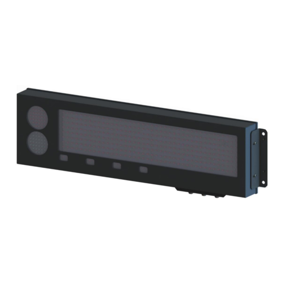
1. Specification RM-470TL remote display Dimensions: 791 mm x 244 mm x 74 mm / 31.14 in x 9.6 in x 2.91 in Digit height: 120 mm / 4.7 in Accepted input voltage range (long-term): 100 ÷ 240 VAC Accepted input voltage range (short-term): 85 ÷... -
Page 4: Rm-470Tl Dimensions
3.2 RM-470TL dimensions 3.2.1 Dimensions of the device with standard side mount Fig. 2 4. Device installation The device should be mounted on a flat surface, with the wires facing down. Only the correct installation of the device ensures its proper operation and the maintenance of the device parameters, such as housing tightness to the declared IP class. -
Page 5: Rm-470Tl Manual Configuration (Communication Protocol Selection)
Autolearn function also detects gross/net measurements if the following markers are sent in the frame: " " - for the Net measurement: from the ASCII table, " " - for the Gross measurement: from the ASCII table. " " In this case, the marker position will also be saved. If, during the operation of the device, the transmitted measurement marker changes, e.g. -
Page 6: Supported Parameters And Baud Rates
The user menu has the following options: 1) info - This option allows you to display the software version. For displays with the Ethernet interface, network layer settings are also provided (IP address, network mask, communication port for KAZEL WagSet software and communication port for the weighing indicator). -
Page 7: Web Browser
4.3.3 Web browser The embedded Web panel allows: - selecting the communication protocol of the weighing indicator, - selecting a pre-configured profile for traffic lights, - changing settings for the displayed measurement unit, - changing the network settings, - checking the version of and updating the display software. The detailed information concerning the Web-panel operation and its capabilities can be found in the device operation manual. -
Page 8: List Of Connectors Of The Display Controller Board
5.2 List of connectors of the display controller board Table 3 lists the controller connectors in RM-470TL remote display. The connectors can be accessed by pulling out the controller board drawer (Fig. 3), without opening the entire device, or removing any connections or parts. NOTICE! The housing should be disassembled only when the power supply is disconnected. -
Page 9: Rm-470Tl Visor
5.3 RM-470TL Visor The mounting visor is fixed with four M5x10 screws included in the set and replaces the standard side mounts shown in Fig. 1. The mounting holes on the sides allow the device to be tilted by 5° and 10°. Fig. -
Page 10: Mounting Rails
5.4 Mounting rails The mounting rails are fitted directly to the rear part of the device housing with the screws included in the set. They enable the installation of mounting clamps, which are used to install the device on a pole. Two mounting rails are provided for each device. -
Page 11: Automatic Brightness Control Of The Remote Display
6. Automatic brightness control of the remote display RM-470TL has a brightness sensor installed on the LED panel as standard. When the automatic control profile is enabled, the device adjusts its brightness responsively to the intensity of daylight. det. A –...
Need help?
Do you have a question about the KAZEL RM-470TL and is the answer not in the manual?
Questions and answers