Advertisement
Quick Links
Advertisement

Subscribe to Our Youtube Channel
Related Manuals for ANNIN ROBOTICS AR3

Summary of Contents for ANNIN ROBOTICS AR3
- Page 1 Model AR3 Robot Manual OPEN SOURCE 6 AXIS ROBOT...
- Page 2 Contents: • Electrical Safety • Overview • Chapter 1 – Bill of Materials • Chapter 2 – Robot Assembly • Chapter 3 – Enclosure Assembly • Chapter 4 – Wiring Diagram • Chapter 5 – Robot Gripper • Chapter 6 – Specifications •...
- Page 3 Electrical Safety ELECTRIC SHOCK HAZARD. The construction of this control enclosure poses potential exposure to alternating current and direct current which has the potential to cause injury or death. This equipment should be constructed and serviced by trained or qualified persons.
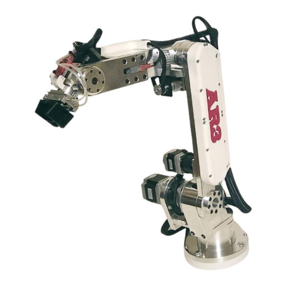
- Page 4 OVERVIEW About building this robot: The AR3 robot is an 6 axis robot project that is free and open source. The following manual is provide so that people can build this 6 axis robot themselves. All software, print files and manuals are available for download on the Annin Robotics website downloads page.
- Page 5 General Robot Assembly notes: • Use medium strength thread locker on all screws. • All belts and chains should be tensioned using moderate tension (do not over tighten or stress belts and chain). Tools Needed: • General hand tools including metric hex key set, locking pliers, wire cutters, wire strippers.
- Page 6 3D Printing Your Robot: This manual shows the construction of the robot using aluminum for the main structural components but the robot can also be constructed using all 3D printed components. The .stl print files for all components are here: https://www.anninrobotics.com/downloads construction illustrated in this manual is the same using either aluminum or 3D printed components - note the following details if using 3D printed components:...
- Page 7 Electrical Enclosure: • 7 AXIS Please note there are several steps that refer to an optional 7 axis travel track. The robot itself only requires 6 drivers and 6 motor plugs/cables. If you would like to build your enclosure to accommodate a 7 axis you can add a 7 driver as well as a 7 plug and cable...
- Page 8 Using Braided Sleeve Several Steps in this manual will call for braided sleeve to be placed over electrical wires. Make sure that as soon as you cut any braided sleeving you use a lighter or flame to carefully melt the ends of the sleeve as shown.
- Page 9 Note that I have found it helpful to strip 10mm of insulation off of wire and then fold wire over on itself before inserting into quick disconnect. This ensures a tight wire fit into terminal. After crimping always pull on wire and make sure you have a good crimp.
- Page 10 Soldering Wire Connections Several steps in this manual will call for soldering and heat shrinking wire connections together. Strip wire ends of both wires and twist wire strands. Insert length of heat shrink tube over one of the wire ends. Use soldering iron and rosin core electrical solder to pre apply solder to the...
- Page 11 Use soldering iron to melt solder on both wire ends so that wire ends are overlapping and solder forms a complete bond between the two wire ends. Slide the heat shrink tube over the solder joint and then use a lighter flame to shrink the tubing over the joint.
- Page 12 Robot Rest Position: Please note that stepper motors when not powered will go limp or drift downward and not always support the robot arm to stay in position when unpowered. When the robot is not powered on it should always be parked in a vertical position with J2 straight up and then J3 straight up –...
- Page 13 CHAPTER 1 BILL OF MATERIALS...
- Page 14 Structural Components Parts shown are made from aluminum but you can also 3D print the structural components if you are building a fully 3D printed robot. See downloads page for .stl print https://www.anninrobotics.com/downloads files. (see note below on J4 main shaft as this part cannot be 3D printed) J1 BASE PLATE J1 TURRET HOUSING J1 SPINDLE...
- Page 15 J2 TURRET HOUSING J2 ARM J2 DRIVE SPINDE J2 TENSION RING...
- Page 16 J1 & J3 MOTOR MOUNTS J2 MOTOR SUPPORT J3 BEARING CUP J3 SPINDLE...
- Page 17 J3 SPINDLE RETAINER J4 TURRET HOUSING J4 MAIN SHAFT J5 MOTOR MOUNT (see note below on making your own J4 main shaft if you are not using aluminum parts kit and are 3D printing your robot)
- Page 18 J4 TIMING HUB J4 MOTOR MOUNT J5 HOUSING J5 BELT CARRIER & J5 BELT CARRIER CLAMP...
- Page 19 J5 BEARING POST J5 IDLER TENSION BLOCK J6 MAIN BEARING ARM J6 HOUSING SINGLE PIECE...
- Page 20 J6 BEARING CAP J6 GRIPPER MOUNT Note on J4 Main Shaft: If you are building a 3D printed robot and do not have aluminum parts you will need to purchase a length of aluminum tubing, cut and drill as shown in this drawing.
- Page 21 Covers and Spacers You will need to 3D print the robots covers and spacers. See downloads page https://www.anninrobotics.com/downloads for .stl print files. Covers and spacers can be printed in any color of your choosing – in this robot build I have chosen white covers and red logos.
- Page 22 J2 UPPER AND LOWER ARM COVER J5 SIDE COVER SPACERS J5 SIDE COVER SPACER J5 SIDE COVER CAP...
- Page 23 J6 LIMIT SWITCH TIP J2 & J5 ARM COVER LOGOS J4 MOTOR SPACER – 4mm...
- Page 24 Hardware Components All Bearings, belts, chains, pulleys, sprockets, keys and screws are available on the robot kits page or can be sourced from various suppliers. Qty. (2) 32009 (45x75x20mm) taper roller Qty. (2) 30206 (30x62x17.25mm) taper bearing for J1 - Sourced from Amazon or roller bearing for J2.
- Page 25 Qty.(2) TRD1625 (1.000x1.5625x0.125 Qty.(2) B1616 (1x1-1/4x1 inch) needle inch) thrust washer(1 for J4 and 1 for J6) – roller bearing for - Sourced from Amazon Sourced from McMaster Carr or Ali Express Qty.(2) 3mm x 85mm shaft (you only need Qty.
- Page 26 Qty.(1) 30203 (17x40x13.25mm) taper roller bearing for J6 - Sourced from Amazon or Ali Express...
- Page 27 Amazon or Servo City (there is also a 3D print file for this but I have not tested the 3D printed part in a built robot) NOTE: the Annin Robotics hardware kit comes with a machined aluminum version of this pulley.
- Page 28 Qty.(2) XL 15 tooth 8mm bore pulley (1 for Qty.(1) XL 10 tooth 6mm bore pulley for J4 J1 and 1 for J6) – Sourced from Ebay – Sourced from Ebay Qty.(2) 04B 13 tooth 8mm bore 6mm pitch sprocket for J3 chain – Sourced from McMaster Carr...
- Page 29 Qty.(1) 1” OD aluminum tube (you need a Qty.(1) – 2mm x 2mm keystock (you need length that is 116.3mm long) - Sourced a length 25mm long) – Sourced from from McMaster Carr McMaster Carr You will need to purchase this part only if building a fully 3D printed robot –...
- Page 30 Metric screws needed: Quantity: #4 x .25 Flat Head Screw #6 x .375 Thread Form Screw M3x10 Flat Head Screw M3x10 Set Screw Screw M3x14 Pan Head Screw M3x14 Socket Head Screw M3x18 Socket Head Screw M3x20 Flat Head Screw M3x20 Pan Head Screw M3x25 Pan Head Screw M3x3 Set Screw...
- Page 31 Stepper Motors All motors are available from Stepperonline. There is a link on the robot kits page to a complete discounted motor, driver and power supply kit from Stepperonline. J1 motor SKU: 17HS15-1684D- HG10-AR3 J2 motor SKU: 23HS22-2804D- HG50-AR3...
- Page 32 J3 motor SKU: 17HS15-1684D- HG50-AR3 J4 motor SKU: 11HS20-0674D- PG14-AR3...
- Page 33 J5 motor 17LS19-1684E-200G-AR3 J6 motor SKU: 14HS11-1004D- PG19-AR3...
- Page 34 250W 24V 10A 115/230V Switching Power Supply Power Supply as well as stepper motors package for the AR3 robot is available from Stepperonline DM542T digital stepper driver. You will need (5) of these drivers for axis 1,2,3,5 & 6 of the robot. You will need...
- Page 35 DM320T digital stepper driver. You will need (1) of these drivers for axis 4 of the robot. Stepper drivers as well as stepper motors package for the AR3 robot is available from Stepperonline (1) Bracket for the J4 motor #SKU: ST-M3 https://www.omc-stepperonline.com/...
- Page 36 Electrical & Misc. Components BUD Industries NBF-32026 Plastic ABS NEMA Economy Box. Any appropriate enclosure designed to IP66 of IEC 529 and NEMA 1, 2, 4 and 4x specifications can be used or substituted. A larger enclosure would be ideal but I have found the NBF-32026 to be the most cost effective option.
- Page 37 BUD Industries IPV-1115 IP32 Air Vent, 3.2" x 3.2“ This item is available from Amazon or can be purchased from multiple online sources or the manufacture. https://www.budind.com/ (1) Box #6 x 3/8 thread forming screws.
- Page 38 3D printer using the print file: “8 channel relay mount.STL” which can be found at: https://www.anninrobotics.c om/downloads Under the AR3 print files. Printer settings used for ABS: 3 layer wall thickness 20% infill 220°C nozzle (print setting not critical for...
- Page 39 5 meters of flexible 18awg silicon hook up wire. You will need 1 box containing at least 4 different colors (blue, black, green & red) This item is available from Amazon or multiple online electrical supply vendors. 20ft - 22awg red and black flexible silicone wire.
- Page 40 20ft - 22awg white flexible silicone wire. This item is typically available in 50’ roll so you will have some extra. 18awg 4 conductor cable. This item is typically available in 100’ roll from Amazon or multiple online electrical supply vendors. NOTE: Wire colors are red, white, black and green...
- Page 41 (1) Roll 26awg twisted pair wire 5 meters long. This item is available from Amazon or multiple online electrical supply vendors. 18awg primary electrical wire. The colors used in this manual are white, black, green, brown and blue. This item is available from Amazon or multiple online electrical supply vendors.
- Page 42 (6) 6’ long Ethernet cables. For the robot assembly we will use a yellow, blue and red Ethernet cable. These cables will be cut where part of each cable is used inside the electrical enclosure and the other part is used for the robot. The black, green and white Ethernet cables will not be cut and will be used...
- Page 43 Heat Shrink tube kit. This item is available from Amazon or multiple online electrical supply vendors. Qty. (1) Roll of ½” braided sleeve. Qty. (1) Roll of ¼” braided sleeve. This item is available from Amazon or multiple online electrical supply vendors.
- Page 44 Qty. (2) PG-21 gland nuts. Gland nuts are commonly available in the color black but I have chosen white for this robot build. This item is available from Amazon or multiple online electrical supply vendors. DIN rail and terminal blocks. Color coded kit as the one shown is convenient but not necessary.
- Page 45 Qty.(1) straight lever XV- 152-1C25 limit switch – Sourced from Amazon or Ali Express Qty.(5) roller tip SV-166- 1C25 limit switches – Sourced from Amazon or Ali Express...
- Page 46 AC Rocker Switch 3 Pin IEC320 C14 Inlet Module Plug Fuse. This item is available from Amazon or multiple online electrical supply vendors. Emergency Stop Switch Push Button Switch This item is available from Amazon or multiple online electrical supply vendors.
- Page 47 Qty (3) RJ45 CAT5e Feedthru Panel Mount Jack This item is available from Amazon or multiple online electrical supply vendors. Note: you will also need 3 of these in the robot base (see chapter 1) so there is a total of 6 needed. Qty.
- Page 48 (2) GX16-2 aviation plugs. You will need a total of (2) plugs, (1) cable will be made, (1) socket will be installed in this enclosure and (1) socket will be installed on the robot. This item is available from Amazon or multiple online electrical supply vendors.
- Page 49 (12) 22 awg quick disconnect terminals. (6) 22awg 90° quick disconnect terminals. This item is available from suppliers such as Amazon, Ali Express or any hardware store. You will need (5) 16awg wire ferrules and (20) 22awg ferrules. The ferrule kit shown is a good option if you do not already have a ferrule crimping tool.
- Page 50 Qty. (6) AMT102-V encoder. This encoder is available from Amazon as well as multiple online electrical suppliers such as Digi-Key, Mouser and Arrow. Qty. (3) 3019_0 (50cm high speed encoder cable). This cable will be cut in half yielding (6) encoder pigtails.
- Page 51 8 channel 5vdc relay module. This item is available from Amazon or multiple online electrical supply vendors. Note: Relay module is included in this project for general purpose needs. This relay module can be used to control your gripper or any other number of actuators or solenoids that you require the robot to control from the program...
- Page 52 Teensy 3.5 controller without pins. This item is available from Amazon, multiple online suppliers or https://www.pjrc.com/store/t eensy35.html Arduino Mega 2560 controller. This item is available from Amazon or multiple online electrical supply vendors.
- Page 53 5vdc power supply This item is available from Amazon or multiple online electrical supply vendors. Qty. (1) SMC MHF2-8D1 pneumatic gripper. This is the recommended gripper for the robot however you can use any gripper you like. Please review chapter in this manual on grippers.
- Page 54 3mm OD flexible tubing You will need 3mm pneumatic tubing if using a pneumatic gripper for your robot. This item is available from Amazon or multiple online electrical supply vendors. (2) M3 thread x 3mm tube fitting. You will need 2 of these if using the SMC This item is available from Amazon or multiple online...
- Page 55 CHAPTER 2 ROBOT ASSEMBLY INSTRUCTIONS...
- Page 56 Use M4 tap to thread (2) holes as shown in J1 base enclosure part 1 Epoxy J1 enclosure part 1 and part 2 together as shown. It is recommended that you place both enclosure pieces on flat surface such as a glass table top while epoxy cures.
- Page 57 Secure J1 base plate to J1 enclosure assembly using (2) M4x20 pan head machine screws. NOTE: these screws are meant to hold base plate to enclosure for assembly and transport purposes only – when assembly is complete and you are ready to use your robot you will need to secure robot to table or work surface using 8mm...
- Page 58 Install #32009 bearing on J1 spindle as shown. Insert J1 spindle into turret housing then install the other #32009 bearing on top side of spindle.
- Page 59 Use abrasive saw to cut square head M8 screw down as shown leaving approx. 8mm of threads remaining. Install square head M8 screw into J1 turret platform as shown – make sure square head is tangent to center bolt circle as indicated by dashed line in picture.
- Page 60 Press (x2) #30206 bearing races into the J2 turret housing. If you do not have access to a press place turret housing in oven @ 350° and bearing races in freezer for 60 minutes, quickly remove housing from oven – the cold races will drop into the expanded housing.
- Page 61 Install (2) M6 x 20 socket head screws in front of J2 turret housing going into the J1 platform. Install platform assembly onto J1 spindle assembly and secure with (8) M6 X 14 socket head cap screws.
- Page 62 Install (4) M4 x 10 set screws in the 4 perimeter holes in the platform. These place tension on the upper bearing. Snug the 4 set screws down evenly until there is no play in the bearings. Secure J1 turret assembly to J1 base from the bottom using (8) M4x10 socket head cap screws.
- Page 63 Make sure limit switch flat is facing toward rear as indicated by red lines in this image. In the following steps we will install the J1 Motor. Standard aluminum XL pulleys are not slotted for the 3mm keyway. If you have access to the proper broach tooling it is recommended that you...
- Page 64 Install J1 motor mount to J1 motor using (4) M4x10 flat head screws. Install XL15 tooth 8mm bore drive sprocket on J1 gear motor shaft and tighten set screws. If using un-broached pulley make sure one of the set screws is seated into motor shaft slot.
- Page 65 Install (2) M3x10 set screws in rear of motor mount slots. Install motor assembly onto base and secure with (4) M4 X 20 socket head cap screws and (4) washers but do not fully tighten until after belt is tensioned. NOTE: Make sure (2) 3mm tension holes located on ends of slots are facing...
- Page 66 Install 60T timing hub pulley onto J1 spindle and secure with (4) M6x14 socket head cap screws, then install 180XL037 belt as shown. Make sure the (4) 4mm X 20 socket head cap screws securing the motor to the baseplate are slightly loose so that motor can slide to apply belt tension.
- Page 67 Once belt has moderate tension tighten the (4) 4mm X 20 socket head cap screws securing the motor to the baseplate. Install the green (.197”) AMT-102 encoder sleeve on to the J1 motor as shown. Please review the assembly instructions provided with the AMT-102 encoder.
- Page 68 Use (4) M3x5 flat head screws to mount the ENC- AMT102 base to the top of the J1 motor as shown. Set dip switch settings on AMT-102 encoder as follows: Switch 1 = Off Switch 2 = Off Switch 3 = Off Switch 4 = This sets the encoder to a resolution of 512 steps per...
- Page 69 Install AMT-103 encoder on to J1 motor as shown. Encoder will snap into the plastic base. Cut (3) high speed encoder cables in half yielding a total of (6) encoder plug wire ends. One of them will be used for the J1 motor in the following step –...
- Page 70 Install encoder wire end into J1 encoder as shown. Cut length of ¼” braided sleeve to a length of 23cm (9”) long then route J1 motor and encoder wires through the sleeve. Attach small cable tie as shown near plug end. Leave J1 wire loom off to the side for now, later in this manual, after...
- Page 71 Cut lengths of red, black and white 22awg wire to lengths of 26cm (10”) long. Crimp 90° quick disconnect to the end of each wire. Install wires with quick disconnects onto SV-166- 1C25 roller tip limit switch and then install limit switch onto J1 turret housing as shown.
- Page 72 Cut length of ¼” braided sleeve to length of 19cm (9.5”) long and then install over J1 limit switch wires as shown. Install small cable tie around sleeve at switch end as shown. Leave J1 limit switch wire loom off to the side for now, later in this manual, after connecting J2 &...
- Page 73 Install (2) PG-21 gland nuts into base enclosure as shown. Clear all (6) RJ45 mounting holes using a #41 (2.4mm) drill.
- Page 74 Install (3) RJ45 panel mount jacks as shown and secure with (6) #4 flat head screws. Cut yellow, blue and red Ethernet cables to overall length of 15cm (6”) Note: save remaining end of yellow, blue and red Ethernet cables for use in assembly of the electrical enclosure.
- Page 75 Use a razor blade to carefully score sheathing at end of connector and then gently remove all sheathing. NOTE: be extremely careful when scoring the sheathing that you don’t cut through and damage the wires. Cut off and remove the brown and white pair of wires from each cable and then plug the red, blue and...
- Page 76 Cut (1) length 18awg red wire to 5cm (2”) long. Cut (12) lenthgs of 22awg red wire to 5cm (2”) long. Pre apply solder to the ends of each wire. This is also known as tinning the end of each wire. Use small cable tie to group the (12) 22awg wires together and then insert the...
- Page 77 Solder bundle of wires together as shown and then remove cable tie. Make sure all wire ends are soldered together thoroughly and non are loose or can be removed. Apply heat shrink tubing around solder joint as shown.
- Page 78 Repeat the previous (4) steps using black 22awg wire to create a second wire bundle, but on this bundle of black wires add one extra wire for a total of (13) leads on the -5vdc bundle. Insert the single 18awg wire from both bundles through GX16-2 aviation plug nut and then through...
- Page 79 Solder 18awg wires to GX16-2 aviation plug terminals as shown. GX16-2 aviation plug notch should be facing upward so that the black bundle is on the left side of the plug and the red bundle is on the right side of the plug. Insert plug and tighten nut.
- Page 80 Install large heat shrink tube or electrical tape over 5vdc plug solder joints as shown to avoid exposed terminals inside enclosure. Install J2 spindle into J2 arm as shown using (8) M4x10 flat head screws. (green arrow). Make sure J2 spindle keyway is oriented up as shown (red arrow).
- Page 81 Install #30206 bearing onto J2 spindle as shown. Install M3x10 set screw into J2 spindle as shown but do not thread through to keyway yet.
- Page 82 Install J2 arm assembly into J2 turret housing and then install the other #30206 bearing from opposite side as shown. Install J2 tension ring and secure with (6) M3x10 flat head screws. Make sure tension ring is 90° to the J2 arm and that the keyway slot in tension ring aligns with keyway slot in J2 spindle.
- Page 83 Install (4) M4x5 set screws and tighten until there is no play in J2 bearings. These set screws set the bearing tension – remember to apply loctite to set screw threads. Cut lengths of red, black and white 22awg wire to lengths of 61cm (24”) long.
- Page 84 Install wires with quick disconnects onto SV-166- 1C25 roller tip limit switch and then install limit switch onto J2 turret housing as shown. Use (2) M3x14 socket head or Philips pan head screws to secure switch to housing. Be sure to connect wires as follows: •...
- Page 85 AR2 robot – We will now pass the J2 motor wires and encoder wires through this hole on the AR3 robot so having it a larger size will be helpful. Remove the (4) M4 cap screws and lock washers from head of J2 gear motor.
- Page 86 Install J2 motor mount over J2 motor gear box housing as shown. Make sure motor wires are facing to the right (red arrow). Carefully re-install J2 gearbox motor shaft bearing assembly as shown and tighten the M4 cap screws. Then turn motor rear shaft by hand until the main shaft keyway is facing upward as shown.
- Page 87 Remove one of the factory M4 screws holding the J2 motor to the J2 gearbox. Replace factory screw with M4x35 Philips head pan screw, then place (6) M4 washers over screw threads on gear box side as shown. Save one of the factory screws as we will utilize it in a future step.
- Page 88 Repeat this process for the remaining (3) screws replacing the factory screws one at a time with M4x35 pan head screws and placing (6) M4 washers over each screw post. Slide J2 motor mount plate over the M4x35 screw posts as shown and then install and tighten M4 washer and nut.
- Page 89 Install J2 motor assembly onto robot sliding the J2 motor shaft into the J2 spindle. Install and tighten (3) M6x18 flat head screws securing the J2 motor mount plate to the J1 base platform. Make sure there is approx. 1mm gap between the J2 gearbox motor housing and the J2 tension ring set screws as shown.
- Page 90 Install and snug M6x20 cap screw in J2 motor support plate as shown. NOTE: do not over tighten and deform gear box housing. This only needs to be tight enough to locate gearbox radially. Tighten the M3 set screw for the J2 spindle. With the J2 arm in a vertical position you can access the set screw...
- Page 91 Install the Blue (.315”) AMT-102 encoder sleeve on to the J2 motor as shown. Please review the assembly instructions provided with the AMT-102 encoder. Use (4) M3x5 flat head screws to mount the ENC- AMT102 base to the top of the J1 motor as shown.
- Page 92 Set dip switch settings on AMT-102 encoder as follows: Switch 1 = Off Switch 2 = Off Switch 3 = Off Switch 4 = This sets the encoder to a resolution of 512 steps per revolution or 1024 PR for both channels.
- Page 93 Install encoder wire end into J2 encoder as shown. Trim J2 motor and encoder wires to a length of 20cm (8”) long.
- Page 94 Cut Red, Black, Blue & Green 18awg wires to a length of 56cm (22”) long. Solder and heat shrink 22” long extension wires to the J2 motor wires as shown. Be sure to match colors so that red goes to red and so...
- Page 95 Wrap ends of J2 extension wires with tape and then use a marker to put (2) stripes on each wiring indicating the wires are for joint 2 so that you will know these are for J2 when wires have been routed inside enclosure Cut 26awg shielded 4 conductor control cable to a...
- Page 96 Solder and heat shrink the J2 encoder wires to the 26awg control wires as follows: Red goes to red • Black goes to black • White goes to white • • Brown goes to yellow The green wire coming from the encoder will not be used.
- Page 97 Cut length of ¼” braided sleeve to 13cm (5”) long. Tape ends of wires and then slide braided sleeve over J2 motor wires and encoder cable up to motor and encoder and then secure with a small cable tie (red arrow). Feed J2 wires through J2 motor mount plate side hole as shown.
- Page 98 Press (1) #30204 bearing race into the J3 bearing cup. Secure J3 bearing cup and race to end of J2 arm using (6) M3x20 flat head screws.
- Page 99 Install 8mm keyed shaft with 2x2mm keystock into J3 spindle as shown. • 8mm shaft should be 50mm long. 2x2mm keystock should • be 25mm long. Secure shaft and key in position with M3x4 set screw. Install 35x52x4 thrust bearing and washers onto J3 spindle as shown.
- Page 100 Insert J3 spindle and bearing assembly into J2 arm as shown. While holding the J3 spindle and bearing in place insert #30204 bearing over J3 spindle shaft as shown.
- Page 101 Install J3 spindle retainer and secure with (4) M3x10 flat head screws. Tension screws so that there is no play in bearing but not too tight that the J3 shaft does not rotate smoothly. NOTE: don’t forget to use small amount of medium strength loctite on screw threads.
- Page 102 Use 4mm tap to thread (2) holes in each sprocket. Install 13 tooth sprocket on the J3 spindle shaft and secure with (2) M4x5 set screws as shown. Do not forget to apply loctite to set screws. Blank low cost sprockets are not slotted for the 2mm keyway.
- Page 103 In the following steps we will install the J3 Motor. Standard blank sprockets are not slotted for the 3mm keyway. If you have access to the proper broach tooling it is recommended that you broach the pulley for a 3mm slot. Alternatively you can use a pair of locking pliers to remove the key stock from...
- Page 104 Install (2) M3x14 cap head screws into tension slot holes on J3 motor mount. Install 13 tooth 8mm bore drive sprocket on J3 gear motor shaft as shown and tighten set screws. If using un-broached pulley make sure one of the set screws is seated into motor shaft slot.
- Page 105 Cut length of 04B - 6mm chain down to length of 20-3/4” long (52.7cm). It should have 43 links. Install master link in 04B roller chain as shown.
- Page 106 Install chain over top sprocket then insert J3 motor assembly and drop J3 motor sprocket into chain. J3 motor assembly will be hanging from chain – motor will be secured in next step. Secure J3 motor assembly to J2 arm using (4) M4x20 socket head cap screws and (4) washers.
- Page 107 Tighten M3 tension screws until there is moderate tension on chain. After chain is tensioned tightened finish securing the J3 motor mount by tightening the (4) M4x20 motor mount screws. Apply grease to chain and sprockets as shown.
- Page 108 Install J2 upper side cover and upper side cover spacer as shown. Secure with (2) M3x25 Philips head pan screws. Install J2 lower side cover and side cover spacer as shown. Install remaining M3x25 Philips head pan screws. There are a total of (16) screws.
- Page 109 Secure AR3 logo into recess in J2 side cover using epoxy. Cut lengths of red, black and white 22awg wire to lengths of 107cm (42”) long. Crimp quick disconnect to the end of each wire.
- Page 110 Install wires with quick disconnects onto SV-166- 1C25 roller tip limit switch Be sure to connect wires as follows: • Black to NC2 terminal • Red to NO3 terminal White to COM1 terminal • Cut length of ¼” braided sleeve to length of 41cm (16”) and slide over the 22awg wires up to limit switch as shown.
- Page 111 Secure J3 limit switch wire to top of J3 gearbox housing using 2 medium size cable ties (red arrows). Then route the J3 limit switch wire behind the J3 motor and then around the front of the J2 motor gear box (yellow arrow).
- Page 112 Cut Red, Black, Blue & Green 18awg wires to a length of 56cm (22”) long. Solder and heat shrink 56cm (22”) long extension wires to the J3 motor wires as shown. Be sure to match colors so that red goes to red, black goes to black and so on.
- Page 113 Install the green (.197”) AMT-102 encoder sleeve on to the J3 motor as shown. Please review the assembly instructions provided with the AMT-102 encoder. Use (4) M3x5 flat head screws to mount the ENC- AMT102 base to the top of the J3 motor as shown.
- Page 114 Set dip switch settings on AMT-102 encoder as follows: Switch 1 = Off Switch 2 = Off Switch 3 = Off Switch 4 = This sets the encoder to a resolution of 512 steps per revolution or 1024 PR for both channels.
- Page 115 Cut 26awg shielded 4 conductor control cable to a length of 56cm (22”) long. Carefully score outer jacket with razor knife, remove 2.5cm (1”) of the grey outer jacket on both ends of cable. (be careful to not damage wires or shielding when removing jacket.
- Page 116 Use a marker to put (3) stripes on opposite end of cable indicating the cable is for joint 3 so that you will know these are for J3 when wires have been routed inside enclosure.
- Page 117 Cut length of ¼” braided sleeve to length of 26cm (10”) long (red arrow). Wrap ends of J3 motor wires and J3 encoder wires with painters tape (blue arrow) and then route all J3 wires through braided sleeve. Secure braided sleeve to wires at motor base using small cable tie (yellow arrow).
- Page 118 Cut length of ½” braided sleeve to length of 51cm (20”) long. Wrap ends of all J2 and J3 wires with painters tape and then route all wires through braided sleeve. Wrap small cable tie around end of braided sleeve so that it is tight to the bundle of wires (yellow arrow).
- Page 119 Route red, black, green & blue 18awg J3 motor wires through nut from a GX16-4 aviation plug and then through the bottom left hole of enclosure as shown. Solder motor wires to GX16-4 aviation plug as shown. View from back of connector with notch up solder black to upper left, green to upper right, red to...
- Page 120 Install J3 plug into enclosure and tighten nut from backside. Route red, black, green & blue 18awg J2 motor wires through nut from a GX16-4 aviation plug and then through the middle left hole of enclosure as shown.
- Page 121 Solder motor wires to GX16-4 aviation plug as shown. View from back of connector with notch up solder black to upper left, green to upper right, red to lower left and blue to lower right. Install J2 plug into enclosure and tighten nut from backside.
- Page 122 Route red, black, green & blue J1 motor wires through nut from a GX16-4 aviation plug and then through the middle left hole of enclosure as shown. These are the factory wires from the J1 motor. Solder motor wires to GX16-4 aviation plug as shown.
- Page 123 Install J1 plug into enclosure and tighten nut from backside. Solder and heat shrink the J1 encoder A-B wires to the Red Ethernet cable A-B wires for J1 (orange – orange stripe). Encoder white wire goes • to Red Ethernet cable - white with orange stripe wire.
- Page 124 Solder and heat shrink the 5vdc red and black wires from the J1 encoder to one of the red and black 5vdc source bundle wires. Black wire from J1 • encoder goes to one of the black wires from - 5vdc bundle.
- Page 125 Solder and heat shrink the 5vdc red and black wires from the J2 encoder cable to one of the red and black 5vdc source bundle wires. Black wire from J2 • encoder goes to one of the black wires from - 5vdc bundle.
- Page 126 Solder and heat shrink the 5vdc red and black wires from the J3 encoder to one of the red and black 5vdc source bundle wires. Black wire from J3 • encoder goes to one of the black wires from - 5vdc bundle.
- Page 127 Solder and heat shrink the 5vdc red and black wires from the J1 limit switch to one of the red and black 5vdc source bundle wires. Black wire from J1 limit • switch goes to one of the black wires from -5vdc bundle.
- Page 128 Solder and heat shrink the 5vdc red and black wires from the J2 limit switch to one of the red and black 5vdc source bundle wires. Black wire from J2 limit • switch goes to one of the black wires from -5vdc bundle.
- Page 129 Solder and heat shrink the 5vdc red and black wires from the J3 limit switch to one of the red and black 5vdc source bundle wires. Black wire from J3 limit • switch goes to one of the black wires from -5vdc bundle.
- Page 130 Secure J4 turret housing to J3 spindle using (2) M4x14 flat head screws (center) and (4) M4x10 cap screws (outer). Secure J4 timing hub to J4 main shaft using (4) M4x5 set screws. Note that one of the set screws needs to seat into the 2 hole in J4 main shaft.
- Page 131 Install (1) TRD1625 (.126” thick) bearing washer over J4 main shaft and into J4 timing hub recess as shown. Install (1) NTA1625 (1” ID) need roller bearing over J4 main shaft and into J4 timing hub recess as shown.
- Page 132 Install (1) TRA1625 (.032” thick) bearing washer over J4 main shaft and into J4 timing hub recess as shown. Install J4 tube / timing hub assembly into the J4 turret as shown. Make sure bearings are fully seated in timing hub recess and flush to J4 turret housing.
- Page 133 Install (1) M3x5 socket head cap screw into J5 motor housing as shown. This screw serves as a timing lug for the J4 limit switch. Secure J5 motor mount using (4) M3x18 socket head cap screws. Note the motor connector is facing downward (red arrow) and the timing lug screw is 90°...
- Page 134 Install (1) TRA1625 (.032” thick) bearing washer over J5 motor shaft and into J5 motor mount recess as shown. Install (1) NTA1625 (1” ID) need roller bearing over J5 motor shaft and into J5 motor mount recess as shown.
- Page 135 Install (1) TRA1625 (.032” thick) bearing washer over J5 motor shaft and into J5 motor mount recess as shown. Install J5 motor assembly into J4 main tube as shown. Be careful that bearings stay in place in J5 motor mount and slide over the end of the J4 main tube.
- Page 136 Install (4) M4x5 set screws into J4 timing hub in locations shown with red arrows. Don’t forget to apply loctite to set screws and then apply light tension to each screw, these screws will apply tension on all of the J4 bearings.
- Page 137 Install Nema 11 motor mount bracket as shown, place the 3D printed part “J4 motor spacer – 4mm” between the bracket and the aluminum. Secure with (4) M3x14 socket head cap screws. The covers and spacers print files comes with 2mm, 3mm, 4mm and 5mm thicknesses of the “J4 motor spacer”...
- Page 138 Install XL 10 tooth 6mm bore drive pulley onto J4 motor shaft and secure with (2) M3x4 set screws. Install 84XL037 timing belt. Place belt over the 10 tooth J4 motor pulley and then up over the main shaft sprocket – rotate the J5 / J4 assembly as belt rolls onto sprocket.
- Page 139 Countersink the (3) holes in POM nut that came with the J5 linear screw motor. Install POM nut into the J5 carrier as shown and secure with (3) M3x10 flat head screws.
- Page 140 Before installing the 3mm shaft bearings into the J5 carrier check to see that they slide easily and smoothly over the 3mm rods. DO NOT FORCE BEARINGS OVER RODS • the inner ball bearings can be dislodged if forced. If variation / tolerance in either bearings, rods or rod surface finish result in a slightly tight fit or a rough fit...
- Page 141 Install (4) LM3UU 3mm shaft bearings into J5 carrier. Install 2 bearings per side – pictures shown 2 installed on front side of carrier, also install 2 on back side. Secure bearings in carrier using (4) M3x4 set screws.
- Page 142 NOTE ON 3mm ROD DIAMETER The diameter of the 3mm rod can vary slightly depending on suppliers. Measure you rods and make sure they are approx. 2.98mm in diameter and that the 3mm bearings slide on to them easily. DO NOT FORCE BEARINGS ONTO ROD If you find your rods are slightly larger –...
- Page 143 Use abrasive saw to cut (2) 3mm linear rods down to 85mm in length. Place J5 carrier inside of the J5 housing, then install (2) 3mm linear rods through the J5 carrier bearings as shown.
- Page 144 Temporarily install M4x8 socket head cap screw fully threaded into hole as shown (red arrow) – this will prevent the 3mm rod from going too deep and blocking the hole. Finish sliding the 3mm rods into place as shown. Secure both 3mm rods in place using (2) M3x6 set screws –...
- Page 145 Install the J5 idler tension block and secure with (2) M3x8 socket head cap screws. Install HK1612 bearing over the J5 bearing post as shown.
- Page 146 Secure the bearing post and bearing to the J5 tension block using (1) M4x14 socket head cap screw as shown. Install 688Z bearing in end of J5 housing as shown and then secure with (2) M3x6 set screws from each side.
- Page 147 Spin J5 housing assembly onto J5 motor lead screw as shown. Slide J5 housing assembly forward onto J4 main tube until fully seated against J4 timing hub. Note on robot weight: from this point forward as we add more components to the upper robot arm the J3 motor will at some point start to sag or drift downward and not...
- Page 148 Install M3x6 set screw (red arrow) to secure J5 housing to J4 main tube, make sure screw threads into hole in J4 main shaft to ensure clocking is correct. Install the green (.197”) AMT-102 encoder sleeve on to the J4 motor as shown.
- Page 149 Use (2) M3x5 flat head screws to mount the ENC- AMT102 base to the top of the J4 motor as shown. Set dip switch settings on AMT-102 encoder as follows: Switch 1 = Off Switch 2 = Off Switch 3 = Off Switch 4 = This sets the encoder to a resolution of 512 steps per...
- Page 150 Install AMT-103 encoder on to J4 motor as shown. Encoder will snap into the plastic base. Install encoder wire end into J4 encoder as shown.
- Page 151 Cut J4 motor and encoder wires down to length of 5cm (2”) as shown. Cut Red, Black, Blue & Green 18awg wires to a length of 107cm (42”) long...
- Page 152 Solder and heat shrink 107cm (42”) long extension wires to the J4 motor wires as shown. Be sure to match colors so that red goes to red and so Tape ends of J4 motor wires together and use marker to mark wires with (4) stripes so that you will know these are for J4 when wires have been routed...
- Page 153 Solder and heat shrink the J4 encoder wires to the 26awg control wires as follows: Red goes to red • • Black goes to black White goes to white • Brown goes to yellow • The green wire coming from the encoder will not be used.
- Page 154 Secure wires and sleeve to left side of J4 motor using large cable tie as shown (red arrow). Route J4 wires and sleeve into side slot of upper arm spacer as shown. Make sure there is enough slack or arch in wires that arch comes level with J5 motor mount (dashed line).
- Page 155 Cut lengths of red, black and white 22awg wire to lengths of 112cm (44”) long. Crimp quick disconnect to the end of each wire. Install wires with quick disconnects onto SV-166- 1C25 roller tip limit switch Be sure to connect wires as follows: Black to NC2 terminal •...
- Page 156 Install the J4 limit switch onto J4 turret housing as shown. Use (2) M3x14 socket head or Philips head pan screws to secure switch inside of arm. Route J4 limit switch wires and braided sleeve over J4 gear box to other side of J4 motor.
- Page 157 Install the green (.197”) AMT-102 encoder sleeve on to the J5 motor as shown. Please review the assembly instructions provided with the AMT-102 encoder. Use (4) M3x5 flat head screws to mount the ENC- AMT102 base to the top of the J5 motor as shown.
- Page 158 Set dip switch settings on AMT-102 encoder as follows: Switch 1 = Off Switch 2 = Off Switch 3 = Off Switch 4 = This sets the encoder to a resolution of 512 steps per revolution or 1024 PR for both channels.
- Page 159 Install encoder wire end into J5 encoder as shown. Cut J5 motor wires to length of 26cm (10”) long – (red arrow) Cut J5 encoder wires to length of 5cm (2”) long – (yellow arrow)
- Page 160 Cut Red, Black, Blue & Green 18awg wires to a length of 97cm (38”) long Solder and heat shrink 94cm (37”) long extension wires to the J5 motor wires as shown. NOTE: The J5 motor wires are not the standard colors – make connections as follows: Red motor wire (A+) to Black •...
- Page 161 Cut 26awg shielded 4 conductor control cable to a length of 110cm (43”) long. Carefully score outer jacket with razor knife, remove 2.5cm (1”) of the grey outer jacket on both ends of cable. (be careful to not damage wires or shielding when removing jacket.
- Page 162 Cut length of ¼” braided sleeve to length of 28cm (11”) long. Route braided sleeve over J5 motor and encoder wires as shown. Secure sleeve with small cable tie (red arrow) Secure wires and sleeve to left side of J5 motor using large cable tie as shown (red arrow).
- Page 163 Route J5 motor/encoder wires into upper J2 arm spacer access as shown. Make sure J5 motor/encoder wires have an arch that is 3cm (1.25”) higher than the J4 wires arch. Press #30203 taper roller bearing race into J6 main bearing support arm.
- Page 164 Secure J6 main bearing arm to J5 housing using (6) M4x18 flat head screws. Install #30203 taper roller bearing onto J6 housing side post.
- Page 165 Install (1) TRD1625 (.126” thick) bearing washer into J6 bearing cap recess as shown. Install (1) NTA1625 (1” ID) need roller bearing into J6 bearing cap recess as shown.
- Page 166 Install (1) TRA1625 (.032” thick) bearing washer into J6 bearing cap recess as shown. Install J6 housing from left side as shown and then install the J6 bearing cap (with bearings) from the right. Secure bearing Cap to J6 housing using (1) M6x14 socket head cap screw.
- Page 167 Install (6) M4x5 set screws in perimeter of bearing cap. These set screws will apply tension on J6 bearings. Set tension evenly on all set screws so there is no play J6 housing rotation but also that it rotates smoothly. Use M3 tap to thread the front (6) holes in J5 side cover (red arrows).
- Page 168 Use #30 (.128” or 3.25mm) drill bit to clear the rear (9) holes on J5 side cover spacer. Install J5 side cover as shown, temporarily install (2) M3x25 philips head pan screws to hold side cover in place.
- Page 169 Use countersink to add chamfer to ID of XL15 pulley as shown (red arrow). Depending on manufacturer or supplier stock availability the OD of XL15 flange may vary. Make sure your XL15 sprockets flange OD is between 28mm and 30mm.
- Page 170 If your XL15 pulleys flanges are slightly large you can use belt sander or hand file to reduce the flange diameter. This is a non-critical dimension, it just needs to fit inside the J5 spacer. Install XL15 pulley onto J6 housing post as shown.
- Page 171 Manually rotate the J5 motor lead screw until J5 carrier is all the way forward as shown. Cut lengths of red, black and white 22awg wire to lengths of 127cm (50”) long. Crimp quick disconnect to the end of each wire. Install wires with quick disconnects onto SV-166- 1C25 roller tip limit switch...
- Page 172 In the next steps we are going to install the J5 limit switch, when installed we want the roller tip of the limit switch to make contact with the leading edge of the J5 carrier. The red star in this photo shows the location in which we want the roller tip to make contact with the...
- Page 173 With limit switch installed such that switch clicks or makes contact just as J5 carrier makes the forward position install (2) M4x10 set screws (red arrows) to secure limit switch into position. Set screws should be snug and keep limit switch secured but not too tight –...
- Page 174 Install 150XL belt over J6 pulley and J5 idler bearing. Make sure the hole drilled in belt is aligned with the J5 carrier and install (1) M3x8 cap screw through belt and threaded into J5 carrier clamp as shown (red arrow).
- Page 175 J6 housing to perfect zero – this will also be covered in the startup and calibration video for the AR3 robot. Manually rotate the J5 motor lead screw until the J6 housing is at approx. a 45°...
- Page 176 Install AR3 logo into recess in J5 cover cap and secure with epoxy. Install J5 spacer and J5 side cap as shown and secure to J5 housing using (8) M3x25 Philips head pan screws (red arrows).
- Page 177 Install (6) M3x20 Philips pan head screws in front section of cap (red arrows) securing the cover cap and spacer to the rear side cover. Cut length of ¼” braided sleeve to length of 10cm (4”) long. Route braided sleeve over J5 limit switch wires as shown.
- Page 178 Route J5 limit switch wires through J5 spacer passage so that sheething enters the shorter tube on the side and then the red, black and white wires exit the rear tube as shown. Tape ends of J5 limit switch wires together and use marker to mark wires with (5) stripes so that you will know these are for J5 when...
- Page 179 Install the green (.197”) AMT-102 encoder sleeve on to the J6 motor as shown. Please review the assembly instructions provided with the AMT-102 encoder. Use (2) M3x5 flat head screws to mount the ENC- AMT102 base to the top of the J6 motor as shown.
- Page 180 Set dip switch settings on AMT-102 encoder as follows: Switch 1 = Off Switch 2 = Off Switch 3 = Off Switch 4 = This sets the encoder to a resolution of 512 steps per revolution or 1024 PR for both channels.
- Page 181 Install encoder wire end into J6 encoder as shown and then cut encoder wires down to the same length as the motor wires (15cm). Cut Red, Black, Blue & Green 18awg wires to a length of 130cm (52”) long...
- Page 182 Solder and heat shrink 130cm (52”) long extension wires to the J6 motor wires as shown. Be sure to match colors so that red goes to red and so Tape ends of J6 motor wires together and use marker to mark wires with (6) stripes so that you will know these are for J6 when wires have been routed...
- Page 183 Solder and heat shrink the J6 encoder wires to the 26awg control wires as follows: • Red goes to red • Black goes to black • White goes to white • Brown goes to yellow The green wire coming from the encoder will not be used.
- Page 184 Use epoxy to secure J6 limit switch tip to the straight lever arm limit switch. Make sure it remains flat and fully seated while epoxy cures. You can use a small piece of cardboard or cotton swab to support the rear end of switch while epoxy cures.
- Page 185 Install J6 limit switch onto J6 housing as shown using (2) M3x14 socket head or philps pan head screws. Tape ends of J6 limit switch wires together and use marker to mark wires with (6) stripes so that you will know these are for J6 when wires have been routed inside enclosure...
- Page 186 Run the pneumatic tubing along with all the J6 motor, encoder and limit switch wires. Run the tubing 23cm (9”) past where the encoder and motor wires go into the motor and encoder and then use a small cable tie to temporarily hold them in place as shown.
- Page 187 Feed all J6 wires and pneumatic tubing through the J5 spacer passage as shown. Tuck approx. 3cm (1”) of sleeve inside the leading end of the J5 spacer passage. Remove the cable tie used to hold the pneumatic lines in place and wrap braided sheeth end at J6 wires and tubing outlet with black electrical tape (red arrow).
- Page 188 Route all of the J6 wires down through the wire-way channel on the back of the J2 arm spacer as shown. Be careful not to pull too hard on wires as you are working them down the wire-way along with the J3 and J4 wires.
- Page 189 Tuck 3cm (1”) of the ½” braided sleeve up into the bottom end of the J2 spacer arm wire-way. Once this is done install cable tie through 6mm hole in wire-way, push it back and around wires and sleeve inside wire way and then use needle nose pliers to get it back out the 6mm hole on opposite side.
- Page 190 Route J4-6 wire loom through right gland nut as shown. Temporarily unplug the red Ethernet plug to assist in pulling it through. Make sure to leave amount of slack shown in loom prior to entering the enclosure – the amount of slack should match the amount of slack in the J1-3 loom below it.
- Page 191 Route red, black, green & blue 18awg J6 motor wires through nut from a GX16-4 aviation plug and then through the bottom right hole of enclosure as shown. Solder motor wires to GX16-4 aviation plug as shown. View from back of connector with notch up solder black to upper left, green to upper right, red to...
- Page 192 Install J6 plug into enclosure and tighten nut from backside. Route red, black, green & blue 18awg J5 motor wires through nut from a GX16-4 aviation plug and then through the middle right hole of enclosure as shown.
- Page 193 Solder motor wires to GX16-4 aviation plug as shown. View from back of connector with notch up solder black to upper left, green to upper right, red to lower left and blue to lower right. Install J5 plug into enclosure and tighten nut from backside.
- Page 194 Route red, black, green & blue 18awg J4 motor wires through nut from a GX16-4 aviation plug and then through the top right hole of enclosure as shown. Solder motor wires to GX16-4 aviation plug as shown. View from back of connector with notch up solder black to upper left, green to upper right, red to...
- Page 195 Install J4 plug into enclosure and tighten nut from backside. Solder and heat shrink the J4 encoder A-B wires to the Blue Ethernet cable A-B wires for J4 (orange-orange stripe). Encoder cable white wire • goes to Blue Ethernet cable – orange with white stripe wire.
- Page 196 Solder and heat shrink the 5vdc red and black wires from the J4 encoder cable to one of the red and black 5vdc source bundle wires. Black wire from J4 • encoder goes to one of the black wires from - 5vdc bundle.
- Page 197 Solder and heat shrink the 5vdc red and black wires from the J5 encoder to one of the red and black 5vdc source bundle wires. Black wire from J5 • encoder goes to one of the black wires from - 5vdc bundle.
- Page 198 Solder and heat shrink the 5vdc red and black wires from the J6 encoder cable to one of the red and black 5vdc source bundle wires. Black wire from J6 • encoder goes to one of the black wires from - 5vdc bundle.
- Page 199 Solder and heat shrink the 5vdc red and black wires from the J4 limit switch to one of the red and black 5vdc source bundle wires. Black wire from J4 limit • switch goes to one of the black wires from -5vdc bundle.
- Page 200 Solder and heat shrink the 5vdc red and black wires from the J5 limit switch to one of the red and black 5vdc source bundle wires. Black wire from J5 limit • switch goes to one of the black wires from -5vdc bundle.
- Page 201 Solder and heat shrink the 5vdc red and black wires from the J6 limit switch to one of the red and black 5vdc source bundle wires. Black wire from J6 limit • switch goes to one of the black wires from -5vdc bundle.
- Page 202 Carefully tuck all wires into enclosure. Install base enclosure cap and secure with (6) #6 x3/8 thread forming screws.
- Page 203 Install (1) M4x10 socket head cap screw in lower threaded hole in J6 gripper mount as shown. (This will be the contact for the J6 limit switch) Secure J6 gripper mount to MHF2-8D1 gripper using (2) M3x8 socket head cap screws (red arrows).
- Page 204 Install (2) M3x3 pneumatic barb fittings into gripper pneumatic inlet ports as shown. Install J6 gripper mount assembly onto the J6 shaft as shown and secure with (1) M4x10 set screw. Timing lug set screw should be facing down and pneumatic barb fittings should be on the right.
- Page 205 Install air lines on to pneumatic barb fittings as shown.
- Page 206 CHAPTER 3 ELECTRICAL ENCLOSURE & MOTOR CABLES ASSEMBLY INSTRUCTIONS...
- Page 207 Install backplane into enclosure using (4) supplied screws. On left hinge side of enclosure use marker and straight edge to draw rectangle as shown. Rectangle should measure: 1.875” (48mm) wide 1.125” (29mm) tall Rectangle should be centered in side panel of enclosure and be .75”...
- Page 208 On front panel of enclosure mark (2) points as shown. Points should be 1” (26mm) from bottom. Left point should be 1.5” (38mm) from left hinge side of door. Points should be 1.5” (38mm) apart from each other. On front panel of enclosure draw (3) rectangles as shown.
- Page 209 Mark 7 points on front door of enclosure as shown. Points should be 1.5” (38mm) from left hinge edge. Top point should be 3.5” (89mm) from top. Points should be 1” (25.5mm) apart. Note: 7 (bottom) point is optional for 7 axis travel track.
- Page 210 Mark point in upper left corner of door as shown. Point should be 1.5” (38mm) From top of door. Point should be 1.5” (38mm) From left hinge side of door. Use threaded ring from air vent to trace circle on enclosure door as shown.
- Page 211 Use an oscillating multi tool saw to cut out the hole for the rocker switch module. Use an oscillating multi tool saw to cut out the hole for the air vent and the (3) RJ45 ports.
- Page 212 Drill lower two holes for USB ports using stepped drill bit as shown. Holes should be drilled to size: .875” (22mm) Drill (8) aviation plug holes using stepped drill bit as shown. Holes should be drilled to size: .625” (16mm)
- Page 213 Drill emergency stop button hole using stepped drill bit as shown. Hole should be drilled to size: 1” (25mm) Install rocker switch module and then drill 2 mounting holes as shown using #38 (.108) drill.
- Page 214 Secure rocker switch module using (2) #6 thread forming screws. Install (2) USB panel feedthru jacks and drill mounting holes using #38 (.108) drill.
- Page 215 Secure USB feedthru jacks using (4) #6 thread forming screws. Install (3) RJ45 panel feedthru jacks and drill mounting holes using #38 (.108) drill.
- Page 216 Secure RJ45 feedthru jacks using (6) #6 thread forming screws. Install emergency stop button as shown in upper left corner of enclosure door as shown.
- Page 217 Install air vent as shown in upper right corner of enclosure door as shown. With 24vdc power supply upside down on surface, fold sheet of paper and lay sheet of paper across bottom of power supply as shown.
- Page 218 Use pencil to punch holes through paper where power supply mounting holes are located. This sheet of paper will be used as a template for drilling holes in the enclosure wall. Place template as shown along bottom right wall of enclosure and then use felt pen to mark mounting holes on enclosure wall.
- Page 219 Drill (4) marked holes using #20 or 4mm size drill. Secure power supply to bottom rightof enclosure as shown using (4) 3mm button head cap screws.
- Page 220 Cut DIN rail to length of 5” (127mm) and then install (16) terminal blocks as shown. Cut jumpers strips down to (8) pairs of jumpers as shown.
- Page 221 Install jumpers into terminals as shown. You will now have (8) pairs of cross connected terminals. Alternate jumper position high/low as shown and make sure there is no opportunity for jumpers to touch one another. Secure DIN rail terminal assembly as shown using (2) #6 thread forming screws.
- Page 222 Use 18awg green wire to connect bottom terminal on rocker switch module to first pair of DIN rail terminals as shown. Note: Use crimp slide connector to connect end of wire attached to rocker switch module. Use 18awg white wire to connect second from bottom right terminal on rocker switch module to...
- Page 223 Use 18awg black wire to connect second from top left terminal on rocker switch module to third pair of DIN rail terminals as shown. Note: Use crimp slide connector to connect end of wire attached to rocker switch module. Use 18awg black wire to create jumper and connect 2 middle right terminal on rocker switch as shown.
- Page 224 Use 18awg green wire and connect to bottom of first (ground) pair of DIN terminals. Use 18awg white wire and connect to bottom of second (neutral) pair of DIN terminals. Use 18awg black wire and connect to bottom of third (line) pair of DIN terminals.
- Page 225 At the 24vdc power supply terminals connect the green wire to the ground terminal, connect the white wire to the neutral or “N” terminal and connect the black wire to the line of “L” terminal as shown. Mount 5vdc power supply in the location shown.
- Page 226 Use 18awg green wire and connect second wire to bottom of first (ground) pair of DIN terminals. Use 18awg white wire and connect second wire to bottom of second (neutral) pair of DIN terminals. Use 18awg black wire and connect second wire to bottom of third (line) pair of DIN terminals.
- Page 227 At the 5vdc power supply terminals connect the green wire to the ground terminal, connect the white wire to the neutral or “N” terminal and connect the black wire to the line of “L” terminal as shown. Use 22awg red and black wires;...
- Page 228 Route the black and red wires from 5vdc power supply to the 4 and 5 of DIN rail terminals as shown. Use (1) mounting hole cable tie with #6 thread forming screw to secure wires to backplane and then use (3) adhesive cable tie mounts to secure wires to enclosure walls as shown.
- Page 229 Use 18awg brown and blue wires; at the 24vdc power supply terminals connect the brown wire to the V+ terminal, connect the blue wire to the V- terminal. Route the brown and blue wires from 24vdc power supply to the 6 and 7 of DIN rail terminals as shown.
- Page 230 Connect 18awg blue wire from 24vdc power supply to pair of DIN rail terminals. Connect 18awg brown wire from 24vdc power supply to pair of DIN rail terminals. Place relay mount in position shown and mark 4 mounting holes with marker.
- Page 231 Drill (4) marked holes using #20 or 4mm size drill. Use M3 tap to thread all (4) holes in relay mount.
- Page 232 Secure 8 channel relay module to relay mount using (4) M3 cap screws. Secure relay module and mount assembly to bottom of enclosure using (4) 3mm button head cap screws, (4) 3mm washers and (4) 3mm hex nuts.
- Page 233 Install (1) GX16-2 aviation plug socket in enclosure door in bottom hole above RJ45 connectors as shown. Note: make sure that socket alignment notch is mounted in the up position. Connect length of 22awg black wire to 4 pair of DIN rail terminals (-5vdc).
- Page 234 Connect length of 22awg red wire to 5 pair of DIN rail terminals (+5vdc). Use adhesive cable tie mount and cable ties on left enclosure wall and route wires down left side of enclosure wall and then down to the bottom.
- Page 235 Use adhesive cable mount on bottom of enclosure and route the 2 wires as shown down to bottom of enclosure. Note: cut and strip wire ends as shown. Cut and strip ends from (2) female end breadboard jumper wires as shown. One jumper should be red and the other black.
- Page 236 Slide length of 2mm heat shrink tube over each wire. Use soldering iron and silver bearing rosin core electrical solder to solder ends of red and black 5vdc supply wires to ends of female bread board jumper wires as shown.
- Page 237 Slide heat shrink tube over solder joints and then use head gun to shrink tubing around joint. Connect red wire female connector to VCC terminal of relay module. Connect black wire female connector to GND terminal of relay module. Secure wires to base of enclosure using adhesive mount cable tie as shown.
- Page 238 Install Stepper drivers as shown along left side of enclosure and secure to backplane using #6 thread forming screws. Starting at the top install • (3) DM542T drivers for axis 1,2 &3. Then install (1) DM320T • driver for axis 4. •...
- Page 239 Connect 18awg brown wire from 7 pair of DIN rail terminals (+24vdc) to bottom terminal on E-Stop button as shown. NOTE: Leave enough slack so that door will open and close fully. Connect 18awg brown wire from top terminal on E-Stop button to 5 terminal on top stepper driver shown.
- Page 240 Use (1) adhesive cable mount and (3) cable ties to secure brown wires as shown. Cut (6) lengths of 18awg brown wire approx. 70mm long. Then jumper the wires down from the top stepper driver to each stepper driver below. The brown wire should be connected to the 5 terminal on each driver as...
- Page 241 Connect 18awg blue wire from 6 pair of DIN rail terminals (-24vdc) to the 6 terminal on stepper driver as shown. NOTE: 6 terminal on stepper driver is labeled “AC” or “GND” Cut (6) lengths of 18awg blue wire approx. 70mm long.
- Page 242 Cut (6) lengths of 4 strand cable approx. 500mm long Cut a 7 if installing driver for a 7 axis travel track. Use soldering iron and silver bearing rosin core electrical solder to tin the wire ends with solder as shown.
- Page 243 Solder wires as shown to the rear of the GX16-4 aviation plug. The diagram below shows which terminals to solder each wire color. NOTE: this is showing the connector from the backside where wires connect. Repeat this for all motor/driver wires.
- Page 244 Install each GX16-4 with motor driver wire as shown. Mark the ends of each wire so that you can easily identify which driver each wire will go to. The wire from the top plug will go to axis 1, the next down will go to axis 2 and so on down to the bottom plug.
- Page 245 Install adhesive cable mount in on inside lip of door just below center hinge and bundle all driver wires as shown. Connect each driver cable to its corresponding driver. (top cable to the top driver and so on down to the bottom cable to the bottom driver) Connect each color wire to...
- Page 246 This picture shows a close up view of each wire connected to one of the drivers. Use cutters to cut (2) 40 pin PCB header pin strips down to be 24 pins long as shown.
- Page 247 Place Teensy 3.5 board upside down on PCB header pin strips as shown. Use soldering iron and silver bearing rosin core electrical solder to solder each of the PCB female header pins to the terminals on Teensy 3.5 controller.
- Page 248 Each joint should be completely soldered as shown. Teensy 3.5 controller should look like this after soldering both lengths of header pins.
- Page 249 Use (4) 3mm screws to secure Arduino Mega 2560 to 3D printed mount as shown. Use small amount of silicone along center rib to mount Teensy 3.5 to 3D printed mount as shown. Secure Arduino/Teensy mount assembly to backplane using (4) #6 thread forming screws in position shown.
- Page 250 Cut yellow, blue and red Ethernet cables to length of 50cm (20”) Remove 50cm (2”) of outer sheathing and strips ends of each wire. Note: save remaining end of yellow, blue and red Ethernet cables for use in assembly of the robot. Cut and strip ends of (21) jumper wires as shown.
- Page 251 Slide length of 2mm heat shrink tube over each wire. Cut and remove (brown – white/brown stripe) pair of wires from yellow Ethernet cable.
- Page 252 Use soldering iron and silver bearing rosin core electrical solder to solder jumper wires to Ethernet wires as follows: • Blue jumper wire to blue Ethernet wire. White jumper wire to blue • stripe Ethernet wire. Orange jumper wire to •...
- Page 253 Slide heat shrink tubing over each solder joint and then use heat gun to shrink tubing. Repeat the previous 4 steps for the red and blue Ethernet wires as shown.
- Page 254 Connect the red Ethernet cable wires to the Teensy 3.5 as follows: • Yellow to Teensy pin • Orange to Teensy pin Blue to Teensy pin #16 • White to Teensy pin #17 • Grey to Teensy pin #18 • Green to Teensy pin #19 •...
- Page 255 Connect the blue Ethernet cable wires to the Teensy 3.5 as follows: • Yellow to Teensy pin • Orange to Teensy pin Blue to Teensy pin #22 • White to Teensy pin #23 • Grey to Teensy pin #24 • Green to Teensy pin #25 •...
- Page 256 Connect the yellow Ethernet cable wires to the Teensy 3.5 as follows: • Yellow to Teensy pin • Orange to Teensy pin Grey to Teensy pin #28 • Blue to Teensy pin #29 • White to Teensy pin #30 • Green to Teensy pin #31 •...
- Page 257 Use mounting hole cable tie and #6 thread forming screw to secure the red, blue and yellow Ethernet cables to backplane as shown. Connect other end of blue, red and yellow Ethernet cable to RJ45 panel jacks as shown. NOTE: Yellow should be closest to the hinge, red in the middle and blue toward the outside of door.
- Page 258 Cut and strip ends from 22awg red wire as follows: (6) Pieces 80mm long (6) Pieces 45mm long Also cut (1) jumper wire in half and strip end as shown. Use wire ferules and crimper to string all (13) wires together as shown. String groups of (2) 45mm jumpers for each driver with the exception of the axis 4...
- Page 259 The next step is to run 3.3vdc to all the (+3.3v) terminals across all of the stepper drivers. The drivers are NPN or negative switching which means the step and direction pulses will be made by the negative wire and the positive is high or on all the time on all the (+3.3v) terminals.
- Page 260 Connect a pair of breadboard jumper wires (black & white) From Teensy 3.5 to the J1 driver. Black wire: Teensy pin 0 to driver PUL- White wire: Teensy pin 1 to driver DIR- Connect a pair of breadboard jumper wires (grey &...
- Page 261 Connect a pair of breadboard jumper wires (blue & green) From Teensy 3.5 to the J3 driver. Blue wire: Teensy pin 4 to driver PUL- Green wire: Teensy pin 5 to driver DIR- Connect a pair of breadboard jumper wires (yellow &...
- Page 262 Connect a pair of breadboard jumper wires (red & brown) From Teensy 3.5 to the J5 driver. Red wire: Teensy pin 8 to driver PUL- Brown wire: Teensy pin 9 to driver DIR- Connect a pair of breadboard jumper wires (black &...
- Page 263 Connect a pair of breadboard jumper wires (grey & purple) From Teensy 3.5 to the J7 (optional travel track) driver. Grey wire: Teensy pin 12 to driver PUL- Purple wire: Teensy pin 13 to driver DIR- This image shows an overview of the pulse and direction pin wiring to the Teensy 3.5 shown in the...
- Page 264 Connect USB cables to Arduino Mega 2560 and Teensy 3.5 as shown. Connect USB cables to USB panel jacks in door as shown. NOTE: Teensy 3.5 cable should be closest to door hinge.
- Page 265 Connect black jumper wire from GND terminal on Arduino Mega 2560 to GND terminal on Teensy 3.5. Connect extended black jumper wire from neighboring GND terminal on Arduino Mega 2560. Cut and strip opposite end as shown.
- Page 266 Connect extended jumper wire from Arduino 2560 to pair of DIN rail terminals as shown. Note: You should now have GND jumpered from the -5vdc power supply to the Arduino and then to the Teensy so all 3 share a common ground.
- Page 267 This diagram shows connection of the (8) jumper wires to pins 28 through 35 of the Arduino illustrated in the previous step. Extend the (8) jumper wires with another ribbon of jumper wires that are the same colors. This ribbon of jumper wires will again be male to female.
- Page 268 Connect ribbon of jumper wires to 8 channel relay board as follows: Black to relay pin 1 • White to relay pin 2 • Grey to relay pin 3 • • Purple to relay pin 4 • Blue to relay pin 5 •...
- Page 269 Robot Motor Cables You will need to make 6 cables for the robot and a if you are building a travel track. Cut each 18awg 4 conductor cable to whatever length you need – in this example I have cut each cable to 6’...
- Page 270 Strip 5mm sheathing off each wire and then tin each wire with solder as shown. Pre apply solder to each contact on GX16-4 aviation plug connector.
- Page 271 Solder wires to each contact on GX16-4 aviation plug connector – see following steps for wire position. Cables are “straight through” - solder wires on each end of cable mirror image to the other as shown in the sketch and photo shown.
- Page 272 Wrap electrical tape around solder joints to prevent any potential short on connector housing. Slide connector housing over connector and install screw.
- Page 273 Tighten screws on wire clamp. Repeat this process for each cable needed. You will need (6) of these for the robot and (1) if building a travel track.
- Page 274 Robot 5v Power Cable You will also need (1) power cable to supply 5vdc to the robot to power the encoders and the limit switches. Cut length of 18awg 4 conductor cable to whatever length you need, in this example I have cut cable to 6’...
- Page 275 With slot facing up solder red wire on right side and black wire on left side. Do this for both ends of cable. Wrap solder joints with electrical tape to avoid the possibility of solder connections shorting on the aviation plug housing.
- Page 276 Slide aviation plug housing into place over end connector, tighten and install screws. 5vdc power cable is complete.
- Page 277 DIP SWITCH SETTING THESE SETTINGS ARE USED FOR THE FOLLOWING SERIES MOTORS: • J1 - 17HS15-1684D-HG10 1/2 STEPS 1.46 AMP • J2 - 23HS22-2804D-HG50 1/2 STEPS 2.37 AMP • J3 - 17HS15-1684D-HG50 1/2 STEPS 1.46 AMP • J4 - 11HS20-0674D-PG14 1/2 STEPS .5 AMP •...
- Page 278 CHAPTER 4 SCHEMATICS...
- Page 279 Wiring for Drivers and Teensy 3.5...
- Page 280 Wiring for Encoders (Enclosure side)
- Page 281 Wiring for Encoders (Robot side)
- Page 282 Wiring for Limit Switches...
- Page 283 Wiring for Arduino Mega 2560...
- Page 284 Note that the wire colors for the J5 motor are different from the other motors. In the robot assembly chapter the steps for connecting each motor will show how to connect each color wire.
- Page 285 CHAPTER 5 ROBOT GRIPPERS The recommended gripper for the AR3 robot is the SMC model MHF2-8D shown in the Bill of Materials. You can use any pneumatic or electric servo gripper of your choosing. You can modify the J6 flange mount or create your own to use any gripper you like.
- Page 286 If using a servo gripper you would connect your servo to one of the Arduino analog pins 0 through 7 and then use the “Servo” position command button to control your gripper.
- Page 287 If using a pneumatic gripper you would connect a 24vdc solenoid valve to one of the relay outputs (Arduino outputs 28 through 36) and then use the “Set Output On” and “Set Output Off” commands to program relays to control your gripper.
- Page 288 Solenoid valves for controlling pneumatic grippers tend to interrupt the serial connection to the controller. If you find the Teensy or Arduino are losing connection when the solenoid valve actuates install a flyover diode across the solenoid terminals (revers bias). https://en.wikipedia.org/wiki/Flyback_diode...
- Page 289 CHAPTER 6 ROBOT SPECIFICATIONS...
- Page 290 Reach – 24.75 inches (62.9cm) Payload – 4.15 lbs (1.9kg) Accuracy - .01mm Repeatability - .15mm Robot weight (aluminum) – 27lbs (12.25kg) Enclosure weight – 12.5lbs (5.6kg) Max Power Consumption – 8.25amp (198 watts)
- Page 291 CHAPTER 7 STARTUP PROCEEDURE...
- Page 292 AR3 Robot Startup & Troubleshooting Before powering up your control box double check all connections per the wiring schematic. Check continuity on all wires and connectors for each motor, encoder and limit switch. It is imperative that all wire connectors are crimped or soldered carefully and checked with a volt meter.
- Page 293 Connect the motor extension cables and 5vdc power cables from the control enclosure to the robot base as corresponds to the numbers shown below.
- Page 294 Connect (2) USB cables from PC to enclosure as shown below. Please review this video on the startup and software installation: AR3 Startup Video...
- Page 295 As shown in the setup video follow the instruction on this page to install the Teensyduino loader software: https://www.pjrc.com/teensy/td_download.html Install the latest version of the Arduino IDE that is supported by Teensyduino: https://www.arduino.cc/en/main/software Download and install the ARCS_teensy_sketch onto the teensy 3.5 board.
- Page 296 Do not use the auto calibrate button the first time, calibrate each joint one at a time using the individual joint calibration buttons. Have your hand on the E-Stop button the first time so that you can stop the robot and cut power if there is an issue with each limit switch and the robot tries to overdrive the joint.
-
Page 299: Table Of Contents
CHAPTER 8 ROBOT PROGRAMMING 1. COMMUNICATION 2. SPEED / ACCELERATION / DECELERATION 3. JOGGING 4. PROGRAMMING 5. CALIBRATION... -
Page 300: Communication
1. COMMUNICATION Determine which com port your Teensy 3.5 and Arduino Mega is communicating on, you can find this Using Windows device manager, or you can open the Arduino sketch and click on the tools menu and then click on Port. Enter this in the "COM PORT" entry field for the device and click "Set Com". -
Page 301: Speed / Acceleration / Deceleration
2. SPEED / ACCELERATION / DECELERATION The robots speed is set as a percentage of max speed. If you set the speed to 100 this will be the fastest the robot can move. Typical speed for jogging is between 10% and 25%. The acceleration and deceleration settings each have 2 parameters: a duration and a percentage. -
Page 302: Jogging
3. JOGGING In the degrees to jog box enter the number of degrees you wish the robot to move and then press the corresponding "-" or "+" button to move each joint. When jogging in joint mode You can also jog the robot in individual motor steps by checking the "Jog joint in steps"... - Page 303 Press the A button to shift to Cartesian jogging, you then can jog axis X and Y using the D pad. Press the X button again to shift to axis Z. Press the B button to control orientation directions. - jog distance up / down (L & R trigger buttons) - speed up / down (L &...
-
Page 304: Programming
3. PROGRAMMING a. Teaching Positions Always select row in program window where you want the next move or instruction to be placed. From the move type drop down button select the move type you wish to insert and then press the "Teach New Position"... - Page 305 - Move A - Move A is an arc move. You must teach 3 points to form an arc. First select "Move A beg" and teach the start point for your arc - the speed and orientation values for this first point will be applied to the entire arc move.
- Page 306 . Your command window will now have 3 lines of code in a row for each of the 3 points. When a "Move C Start" line of code is executed the program will automatically run the next 2 lines of code to calculate the circle.
- Page 307 - Move SP - SP stands for stored position. In the registers tab there are 16 stored positions you can set. You can set or save the X,Y,Z,Y,P,R for any position you want to execute later or multiple places in your program. When you teach a Move SP the robot will move to the position you have entered for the stored position on the register tab.
- Page 308 - Teach SP - this move command will insert 6 lines into your program which when executed will store the robots current position into a stored position register of your choice. This makes it easier to populate stored positions as you need. The Stored Position button will allow you to enter lines of code that set individual elements of the X,Y,Z,Y,P,R in a stored position.
- Page 309 c. IO - The set output on or set output off buttons allow you to insert a line of code that will turn Arduino IO of your choice on or off (see bottom on input outputs tab for available IO pins on the Arduino Mega).
- Page 310 - the "Create Tab" button allows you to create markers in your program that you can jump or navigate to based on conditions. *note you cannot have 2 tabs with the same number - each tab needs a new number. This functionality is very similar to basic programming.
- Page 311 e. Registers The "Register" button allows you to set a register to a static value or you can add a "++" before the number and the register will then be incremented by the amount. For example, if you just enter a "1" it will always set that register to a value of 1 but if you enter "++1"...
- Page 312 g. Editing lines of code You can select a line of code in you command window and then press the "get selected" button, this will copy that line into the manual entry field. You can now edit the line of code in the manual entry field, some examples might be: changing the stored position number, changing a position, changing the robot speed or acceleration.
-
Page 313: Calibration
4. CALIBRATION a. Auto Calibration Pressing the auto calibration button will auto calibrate all axis. The robot will run to its full limit in the default directions and set each of the joint values accordingly. You can also use the individual buttons to calibrate each axis one at a time. - Page 314 c. fine calibration This feature allows you to set a reference position, so you can check how true your calibration is given an event where you have a bent limit switch or must replace a part of the robot. For example, you can jog the robot to some reference position that you know, perhaps with the robot holding a pointer and going to a known spot, you could then press "teach fine calibration position"...
- Page 315 e. Robot Calibration Values The calibration values allow you to input the freedom of motion for each joint and the number of stepper motor steps to make that stroke happen. If building your own custom robot, you could change these values to match your custom range of motion and stepper gearing.
- Page 316 CHAPTER 9 OPEN LOOP VERSION (AR2)
- Page 317 AR3 version without the expense of purchasing dual shaft motors, or you may want to save some money and not incur the added cost of the encoders. If you would like to build the open loop version of the AR3 you can do so by following the instructions below: •...
Need help?
Do you have a question about the AR3 and is the answer not in the manual?
Questions and answers