Table of Contents
Advertisement
Quick Links
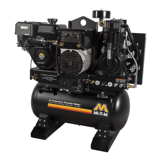
AIR COMPRESSOR/GENERATOR/WELDER
OPERATOR'S MANUAL
PARTS LIST
CAUTION
RISK OF INJURY! READ ENTIRE MANUAL BEFORE OPERATING!
THIS MANUAL IS AN IMPORTANT PART OF THE AIR COMPRESSOR/GENERATOR/WELDER
AND MUST REMAIN WITH THIS UNIT!
Operator's Manual
1
©Copyright 2011, Mi-T-M Corporation®
37-1159-E/S-020123
Advertisement
Table of Contents

Subscribe to Our Youtube Channel
Related Manuals for Mi-T-M AGW-SV14-B


Summary of Contents for Mi-T-M AGW-SV14-B
- Page 1 AIR COMPRESSOR/GENERATOR/WELDER OPERATOR’S MANUAL PARTS LIST CAUTION RISK OF INJURY! READ ENTIRE MANUAL BEFORE OPERATING! THIS MANUAL IS AN IMPORTANT PART OF THE AIR COMPRESSOR/GENERATOR/WELDER AND MUST REMAIN WITH THIS UNIT! Operator’s Manual ©Copyright 2011, Mi-T-M Corporation® 37-1159-E/S-020123...
-
Page 2: Introduction
INTRODUCTION THANK YOU for purchasing a Mi-T-M product. The SERIAL NUMBER is located in the Specification or Identification Numbers section. Accurately record all the READ THIS MANUAL carefully to learn how to operate numbers to help in tracing the machine should it be stolen. -
Page 3: Table Of Contents
CONTENTS INTRODUCTION ..........................2 SAFETY ............................4 RECOGNIZE SAFETY INFORMATION .......................4 UNDERSTAND SIGNAL WORDS .......................4 FOLLOW SAFETY INSTRUCTIONS......................4 CARBON MONOXIDE - POISONOUS GAS ....................4 SAFETY WARNING WHEN REFUELING ....................5 ELECTRICAL HAZARDS ..........................5 RISK OF FIRE OR EXPLOSION .........................6 RISK OF BURSTING ..........................7 RISK OF BREATHING ..........................7 RISK OF BURNS ............................7 RISK OF FLYING OBJECTS........................8... -
Page 4: Safety
SAFETY RECOGNIZE SAFETY INFORMATION This is the safety alert symbol. When you see this symbol on your machine or in this manual, be alert to the potential for personal injury. Follow recommended precautions and safe operating practices. UNDERSTAND SIGNAL WORDS A signal word--DANGER, WARNING or CAUTION--is used with the safety- alert symbol. -
Page 5: Safety Warning When Refueling
SAFETY NEVER run unit inside homes, garages, sheds, or other semi-enclosed spac- es. These spaces can trap poisonous gases EVEN IF you run a fan or open doors and windows. If you start to feel sick, dizzy, or weak while using the unit, shut if off and get fresh air IMMEDIATELY. -
Page 6: Risk Of Fire Or Explosion
SAFETY Plug appliances directly into the unit. Or, use a heavy duty, outdoor-rated extension cord that is rated (in watts or amps) at least equal to the sum of the connected appliance loads. Check that the entire cord is free of cuts or tears and that the plug has all three prongs, especially a grounding pin. -
Page 7: Risk Of Bursting
SAFETY After completion of work, inspect area to ensure it is free of sparks, glowing embers, and flames. Remove stick electrode from holder when not in use. RISK OF BURSTING Serious injury or death may occur from an air tank explosion if air tanks are not properly maintained. -
Page 8: Risk Of Flying Objects
SAFETY RISK OF FLYING OBJECTS Soft tissue damage can occur from the compressed air stream. Always wear safety glasses to shield the eyes from flying debris. Never point the air stream at any part of your body, anyone else or animals. Never leave pressurized air in the unit. -
Page 9: Wear Protective Clothing
SAFETY 9. Beware of using this equipment in confined spaces. Confined spaces, without sufficient fresh air ventilation, can contain dangerous gases. Running gasoline engines in such environments can lead to deadly explosions and/ or asphyxiation. 10. Use extreme caution when lifting this unit. This unit is heavy so proper lifting techniques should be used. -
Page 10: Safety Signs
SAFETY SIGNS MAINTENANCE INSTRUCTIONS INSTRUCCIONES DE MANTENIMIENTO WARNING/ADVERTENCIA REFER TO INSTRUCTION MANUAL FOR LEA LAS INSTRUCCIONES PARA INSTRUCCIONES RIESGO DE QUEMAR RISK OF BURNS DETAILED INSTRUCTIONS. PARTICULARES. El amortiguador y las areas Muffler and adjacent If unit is operated in an excessively dirty or dusty area, increase Si la unidad está... -
Page 11: Controls
CONTROLS 1-Pump Air Filter 10-Weld Amperage Setting 18-20A Toggle Breaker 2-Fuel Cap 11-Generator/Welder Selector Switch 19-20A Push Button Breaker 3-Engine Air Cleaner 12-Min/Max Weld Amperage Toggle 20-Pump Oil Sight Glass Switch 4-Engine Choke 21-Pump Oil Drain 13-Positive Welding Terminal 5-Engine Oil Fill 22-Safety Relief Valve 14-Negative Welding Terminal 6-Engine Oil Drain... - Page 12 CONTROLS 1-Engine Air Cleaner 10-Battery 19-Idle Control Switch 2-Engine Oil Fill 11-Weld Amperage Setting 20-20A Toggle Breaker 3-Pump Oil Drain 12-Generator/Welder Selector Switch 21-Engine Keyswitch 4-Pilot Valve 13-Min/Max Weld Amperage Toggle 22-20A Push Button Breaker Switch 5-Pump Air Filter 23-Safety Relief Valve 14-Positive Welding Terminal 6-Pump Oil Fill 24-Pressure Gauge...
-
Page 13: Installation
INSTALLATION Read safety warnings before setting-up the unit. Ensure the oil level in the unit's pump is adequate. If low, add SAE-30W non-detergent oil. LOCATION: In order to avoid damaging the unit, do not incline the unit transversely or longitudinally more than 10°. WARNING: RISK OF ASPHYXIATION! DO NOT OPERATE IN AN ENCLOSED AREA. -
Page 14: Gasoline Engine
2. Use an extension cord with a 3 hole receptacle and a 3 prong plug at the opposite ends to ensure continuity of the ground protection from the unit to appliance. Mi-T-M strongly recommends that all applicable federal, state and local regulations relating to grounding specifications be checked and followed. LINE TRANSFER SWITCH: If this unit is used for standby service, it must have a transfer switch be- tween the utility power service and the unit. -
Page 15: Engine Oil
INSTALLATION DO NOT PLACE UNIT IN AN AREA WHERE FLAMMABLE GAS VAPORS MAY BE PRESENT. A SPARK COULD CAUSE AN EXPLOSION OR FIRE. ALWAYS STORE FUEL AWAY FROM THE UNIT WHILE IT IS RUNNING OR HOT. WARNING: RISK OF EXPLOSION OR FIRE CAUSING SERIOUS INJURY OR DEATH DO NOT ALLOW THE ENGINE OR MUFFLER TO COME IN CONTACT WITH FLAMMABLE VAPORS, COMBUSTIBLE DUST, GASES OR OTHER COMBUSTIBLE... -
Page 16: Fueling
INSTALLATION TO FILL WITH OIL: 1. Level the engine to ensure accurate inspection and to prevent overfilling. 2. Unscrew the oil gauge (Fig. 1), wipe the dipstick dry. Reinsert the oil gauge back into the oil fill gauge opening. Remove the oil gauge and check the oil level. -
Page 17: High Altitude
INSTALLATION HIGH ALTITUDE At high altitude, the standard carburetor air/fuel mixture will be too rich. Performance will decrease, and fuel consumption will increase. A very rich mixture will also foul the spark plug and cause hard starting. Operation at an altitude that differs from that at which this engine was certified, for extended periods of time, may increase emissions. -
Page 18: Operation
OPERATION PRE-OPERATION: Check the engine oil level before starting. (See engine manual.) Fill the fuel tank according to the engine manual instruction. Pump oil level should be checked before each use. Check the oil level indicator on the pump crankcase. Make certain the oil is in the center of the oil sight glass. -
Page 19: Electrode Chart
OPERATING THE UNIT WARNING: DO NOT USE WORN, DAMAGED, UNDERSIZED, OR POORLY SPLICED CABLES. TURN OFF POWER BEFORE CONNECTING TO WELD OUTPUT TERMINALS. WELD OUTPUT TERMINALS Weld Cable Size** and Total Cable (Copper) Length in Weld Circuit Not Exceeding*** 100 ft (30 m) 150 ft 200 ft 250 ft... -
Page 20: Shutdown
OPERATING THE UNIT SHUTDOWN: 1. Remove all load by turning off electrical appliances and unplugging electric/ welding cords. 2. Move the Engine Switch to the "Off" position. (Refer to the Engine Manual accompanying this unit.) 3. Move the GEN/WELD switch to the GEN position. 4. -
Page 21: Cable Size
OPERATING THE UNIT CABLE SIZE: Equipment damage can result from low voltage. Therefore, to prevent ex- cessive voltage drop between the unit and the equipment, the cable should be of adequate gauge for the length used. The cable selection chart gives the maximum cable lengths for various gauges of wire which can adequately carry the loads shown. -
Page 22: Troubleshooting
TROUBLESHOOTING Symptom Problem Solution Engine will not start. Various engine problems. Refer to the engine manual accompanying your unit. Noisy operation. Loose engine pulley or pump Tighten pulley and or flywheel. flywheel. Lack of oil in the pump. Add correct amount of oil. Check for bearing damage. Carbon deposits on pistons Remove cylinder head and inspect. - Page 23 TROUBLESHOOTING Symptom Problem Solution Oil has milky ap- Water in oil due to condensa- Change oil and move air compressor to a less humid environ- pearance. tion. ment. Unit has no output. Inadequate cord sets or ex- Check cord sets or extension cords capabilities in section tension cords.
-
Page 24: Maintenance
MAINTENANCE MAINTENANCE CHART: To ensure satisfactory operation over an extended period of time, an engine requires normal maintenance at regular in- tervals. The Periodic Maintenance Chart below shows periodic inspection and maintenance items and suitable intervals. The bullet mark designates that the corresponding item should be performed at that interval. NOTE: Some adjustments require the use of special tools or other equipment. -
Page 25: Maintenance
WARNING: RISK OF FIRE OR EXPLOSION. DO NOT USE GASOLINE OIL DRAIN PLUG OR LOW FLASH POINT SOLVENTS TO CLEAN THE ELEMENT. (Fig. 1 MI-T-M) CLEAN THE ELEMENT IN A WELL VENTILATED AREA. ENSURE THAT NO SPARKS OR FLAMES ARE NEAR THE WORKING AREA, THIS INCLUDES ANY APPLIANCE WITH A PILOT LIGHT. -
Page 26: Generator Maintenance
IDLE CONTROL ADJUSTMENT: NOTE: The automatic idle speed is set between 2640 and 2940 RPM. (Fig. 2 MI-T-M) The idle speed has been pre-set at the factory and should rarely require readjustment. We recommend that all adjustments of this nature be made by a Customer Service Representative. - Page 27 MAINTENANCE 2. If the GFCI test correctly, restore power by FIRMLY pushing the “RESET” button back in until you hear or feel a distinctive “click”. IF THE GFCI FAILS TO RESET PROPERLY, DO NOT USE EITHER OUTLET OF THE DUPLEX RECEPTACLE.
-
Page 28: Cleaning And Gapping Spark Plug
To change the gap, bend the side-electrode only, using a spark plug tool. (Fig. 3) Install and tighten the spark plug. Connect the spark plug lead. RECOMMENDED SPARK PLUG: Engine MI-T-M Honda Spark Plug NGK BPR6ES ZFR5F Spark Plug Gap 0.7 - 0.8 mm (0.03 in.) 0.7 - 0.8 mm (0.03 in.) -
Page 29: Wiring Schematic
MAINTENANCE WIRING SCHEMATIC RECTIFIER N° 2-3 SWITCH 2 RECTIFIER N° 1 ROTOR STATOR IMPEDANCE Operator’s Manual... -
Page 30: Wiring Diagram - Agw-Sm14 And Agw-Sv14 (After Serial #20284607)
MAINTENANCE WIRING DIAGRAM - AGW-SM14 AND AGW-SV14 (AFTER SERIAL #20284607) Operator’s Manual... -
Page 31: Wiring Diagram - Agw-Sh22 (After Serial #20284448)
MAINTENANCE WIRING DIAGRAM - AGW-SH22 (AFTER SERIAL #20284448) Operator’s Manual... -
Page 32: Storage
STORAGE SHORT TERM (1-6 MONTHS): 1. Add gasoline conditioner & stabilizer at the specified concentration. 2. Run the unit for two (2) minutes to ensure the mixed fuel is in the entire fuel system. Close the fuel valve and run the unit until it stops. 3. -
Page 33: Specifications
SPECIFICATIONS ITEM SPECIFICATION AGW-SM14 / SV14-30M AGW-SM14 / SV14-B AGW-SH22-20M Mi-T-M Mi-T-M Honda Model R420E / 25V3 R420E / 25V3 GX690 Engine Oil 37.2 oz ./ 32 oz 37.2 oz. / 32 oz 67.6 oz. Max Watts w/o Compressor 5000... - Page 34 STATEMENT OF WARRANTY Mi-T-M warrants all parts, (except those referred to below), of your new unit to be free from defects in materi- als and workmanship during the following periods: For Two (2) years from the date of original purchase:...
- Page 35 SORE , but Mi-T-M cannot deny warranty coverage solely for the lack of receipts. -As the SORE owner, you should be aware that Mi-T-M may deny you warranty coverage if your SORE or a part has failed due to abuse, neglect, or improper maintenance or unapproved modifications.
- Page 36 (10) Mi-T-M shall provide any documents that describe that Mi-T-M warranty procedures or policies within five working days of request by the Executive Officer. (c) WARRANTED PARTS: The repair or replacement of any warranted part otherwise eligible for warranty coverage may be excluded from such warranty coverage if Mi-T-M demonstrates that the engine has been abused, neglected, or improperly maintained, and that such abuse , neglect ,or improper maintenance was the direct cause of the need for repair or replacement of the part.
Need help?
Do you have a question about the AGW-SV14-B and is the answer not in the manual?
Questions and answers