Table of Contents
Advertisement
Quick Links
Installation and Operating Manual
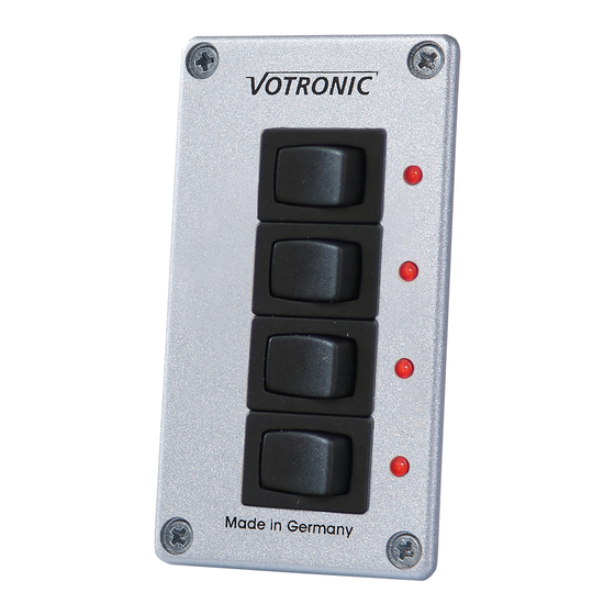
Switch Panel 4 S 12/24
The switch panel 4 S 12/24 contains four individual switches, each with an associated control LED. It is intended for use in
motorhomes, caravans, boats, special and emergency vehicles and can be used in 12 V and 24 V systems. Each switch can
be loaded with a maximum current of 8 A.
Installation
The switch panel 4 S 12/24 is usually installed through a cutout in the wall of a furniture or in a cladding wall and is
attached with four screws. The rear cutout opening should be covered with electrically non-conducting material (e.g. poplar
plywood, 3 mm thickness, or similar material) to ensure efficient protection and full utilization of the storage space, which
might be located behind.
If several VOTRONIC units are applied, use the mapped drilling jig on page 2 for marking. The drilling jig
facilitates positioning and reduces the expenditure of installation, since time-consuming measuring for
alignment is not required.
Connection
The switching inputs with the designation "in 1...4" are switched through by the respective switch to the corresponding
output with the designation "out 1...4".
Protection by fuse of the control inputs might be individually or in groups.
In order to combine several inputs, they can be connected to one another via a wire bridge. The "12 V" or "24 V" terminal is
required to supply the LEDs. In the case of 12 V systems, the terminal marked "12 V" is connected to the negative pole of
the battery or in the case of 24 V systems, the terminal "24 V" is connected to the negative pole of the battery.
Marking
Distinct and abrasion-proof marking can be effected by a VOTRONIC pictograph film (order No. 2112, not included in the
standard delivery scope). This marking pattern contains internationally intelligible signs of the size 8x11 mm, which are
transparent, self-adhesive and punched.
No. 1288
Advertisement
Table of Contents

Subscribe to Our Youtube Channel
Related Manuals for Votronic 4 S 12/24


Summary of Contents for Votronic 4 S 12/24
- Page 1 Installation The switch panel 4 S 12/24 is usually installed through a cutout in the wall of a furniture or in a cladding wall and is attached with four screws. The rear cutout opening should be covered with electrically non-conducting material (e.g. poplar plywood, 3 mm thickness, or similar material) to ensure efficient protection and full utilization of the storage space, which might be located behind.
- Page 2 Connection Plan Front View...
- Page 3 We do not assume any liability for any damage resulting hereof. The liability exclusion is extended to any service being executed by third, which has not been ordered by us in writing. Service is to be effected exclusively by VOTRONIC, Lauterbach. Notes:...
- Page 4 Recycling: At the end of its useful life, you can send us this device for professional disposal: You can find more information about this on our website at www.votronic.de/recycling Delivery Scope 1 ea. Switch Panel 4 S 12/24 •...
Need help?
Do you have a question about the 4 S 12/24 and is the answer not in the manual?
Questions and answers