Advertisement
Quick Links
Installation and Operating Manual
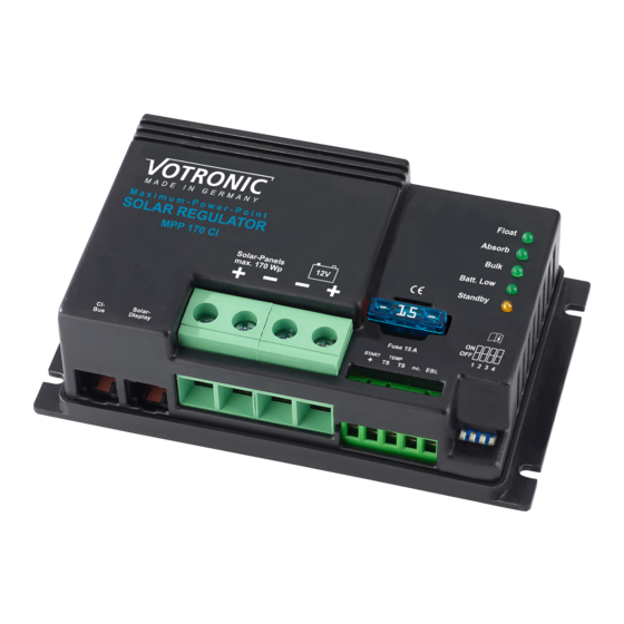
Solar Controller MPP 170 CI
Solar Controller MPP 260 CI
Solar Controller MPP 360 CI
Solar Controller MPP 440 CI
Please read this assembly and operating instructions completely, in particular, page 2
"Safety Regulations and Appropriate Application", before you begin the connection and start-up.
MPP Solar Controller for high-quality campers, caravans and boats.
VOTRONIC Solar Controllers of series "MPP" (Maximum-Power-Point) with characteristic line of charging "IU1oU2" are the
link between solar panel(s) and battery (batteries).
Controllers according to the MPP technology are continuously and automatically calculating the maximum power yield
(MPP) of the solar modules several times per minute. The voltage surplus of the solar module will be transformed to a
higher charging current for the battery (realised by high-frequency switching controller technology with high efficiency).
This surplus of charging current ensures short charging times and the best possible power yield of the solar system.
Working fully automatically and maintenance-free, the solar controllers MPP offer the following functions:
• Increased MPP charging current compared with conventional controllers, due to ultramodern controller technology
(microprocessor) by 10 % to 30 % (efficiency > 95 %). This enhanced capacity shows particularly in cooler times of the
year, such as in case of foggy weather conditions or gloomy diffuse light (winter break).
• Switchable characteristic lines of charging or optimum charging of lead- gel-/dryfit, AGM/fleece or acid/lead-acid
batteries, as well as LiFePO4 batteries (see table 1).
• The charging voltage being free from peaks is controlled in such a way, that any overcharging of the batteries is
excluded.
• Two Battery Charging Ports: Automatic charging of the main battery or leisure battery, as well as support charging
and trickle charging (max. 1 A) of the vehicle's starter battery with overcharge protection.
• Unattended Charging: Standard protection against overload, overheating, reverse battery and back discharge of the
battery (in case of insufficient solar power, such as at twilight, at night etc.).
• Parallel and Floating Operation: Observation of the characteristic lines of charging, even with simultaneous operation
of consumers.
• Overcharge protection: Reduction of the charging current of the battery in case of excessive solar power and full
battery. Immediate recharging in case of power consumption to ensure always the best possible charging state of the
battery.
• Characteristic Line of Charging "IU1oU2": A defined charging boost (U1) avoids harmful acid accumulation (lead) and
provides equalization charge to the individual battery cells (lead and lithium). After that, automatic trickle charging
(U2).
• Charging Cable Compensation: Automatic compensation of voltage losses on the charging cables.
• On-board Mains Suppression Filter: Unproblematic parallel operation with wind-driven and motor-driven generators,
mains supply chargers, dynamos etc.
• Measurement Output for EBL, electroblock possibly existing in the living area of the vehicle: Allows convenient
application of the (solar) current display being installed in the electroblock for supervision of the solar system.
• Terminal "AES" (only MPP 260 CI, MPP 360 CI and MPP 440 CI):
Automatic commutation of refrigerators with "AES" (Automatic Energy Selector, Electrolux/Dometic) from gas
operation to 12 V operation in case of excess solar power.
• Connection for Battery Temperature Sensor (Order No. 2001):
Lead batteries: In case of low outside temperatures, full charging of the weak battery is improved by automatic
adaptation of the charging voltage to the battery temperature, and in case of summery temperatures unnecessary
battery gassing and battery load will be avoided.
LiFePO4 Batteries: Battery protection in case of high temperatures and particularly in case of low temperatures.
Highly recommended, if the battery temperature might drop below 0 °C during operation.
• Ready for connection of the Votronic Solar Displays for optimum control of the system:
LCD Solar Computer S: The LCD display indicates the following values: Battery voltage, charging current,
charging capacity, stored capacity and energy (V, A, W, Ah, Wh), Order No.: 1250.
(12 V / 13 A / 170 Wp)
(12 V / 18.5 A / 260 Wp)
(12 V / 26 A / 360 Wp)
(12 V / 32 A / 440 Wp)
No. 1712
No. 1717
No. 1722
No. 1730
Advertisement

Related Manuals for Votronic MPP 170 CI


Summary of Contents for Votronic MPP 170 CI
- Page 1 "Safety Regulations and Appropriate Application", before you begin the connection and start-up. MPP Solar Controller for high-quality campers, caravans and boats. VOTRONIC Solar Controllers of series "MPP" (Maximum-Power-Point) with characteristic line of charging "IU1oU2" are the link between solar panel(s) and battery (batteries).
- Page 2 We do not assume any liability for any damage resulting hereof. The liability exclusion is extended to any service being executed by third, which has not been ordered by us in writing. Service is to be effected exclusively by VOTRONIC, Lauterbach.
-
Page 3: Connection Plan
The minimum terminal assignment consists of the solar panel inputs ("+" and "-") and the connections to the main battery. Always connect the fuses as close as possible to the batteries (cable protection!). Required Cable Cross-Sections, Notes MPP 170 CI MPP 260 CI MPP 360 CI MPP 440 CI +/- Panel cables, length as required: 2.5-4 mm... - Page 4 - 4 - Mounting: Screw-down the solar controller on an even and hard mounting surface at locations being protected from humidity and near the main/leisure battery to ensure that the length of the battery connection cable is as short as possible. Vertical installation of the controller is highly recommendable (the terminals for solar panel and batteries point down).
- Page 5 - 5 - 4.) Plug-type Connection "Solar Display" (Option, can be connected): 6-pole tip jack for connection of the plug-and-go Votronic Solar Displays for optimum control of the solar system: LCD Solar Computer S: The LCD display indicates the following values: Battery voltage, charging current, charging capacity, stored capacity and energy (V, A, W, Ah, Wh).
-
Page 6: Pilot Lamps
12.80 V, for battery protection and the maximum charging current rate will be halved and safety mode, LED "MPP" is flashing ("Charge" at MPP 170 CI). Any charging data being recorded hitherto will be kept in memory. - Page 7 - 7 - "Standby" (only MPP 170 CI): • Short flashing every 2 sec.: Display of readiness for service in case of missing solar power (at night). All light-emitting diodes are flashing simultaneously: The positions of the selector switches for the main/leisure battery are incorrect. For reasons of safety, the solar controller is switched-off.
- Page 8 - 8 - Table 1: For Main Battery I: How to set the correct charging program for the battery type (design, lead or lithium-iron phosphate technology) Prior to start-up, imperatively set the correct characteristic line of charging being suitable for the battery to avoid battery damages! Set the slide switch ("BOARD Battery") to the desired position for battery I (board battery) using a small screwdriver.
- Page 9 - 9 - Charging Programs for LiFePO4-Batteries: • The charging regulations of the battery manufacturer are absolutely to be observed! • An operation of the unit at a LiFePO4 battery without BMS Battery Management System and without equalization charging of the cells (balancing) as well as safety circuit is not admissible! •...
- Page 10 - 10 - Charging Voltage Rates and Temperature Compensation of Main/Leisure Battery: TS = With Temperature Sensor (Terminals „TS TS“). Mandatory for LiFePO4 batteries! a) Lead "Lead Acid/AGM1", IU1oU2 b) Lead "AGM2", IU1oU2 d) LiFePO4 13,9 V: Lead "GEL", IU1oU2 LiFePO4 14,2 V: LiFePO4 14,4 V: LiFePO4 14,6 V:...
- Page 11 - 11 - Functions at the Main/Leisure Battery "12 V": If solar power is missing (at night), the readiness for service of the controller will be indicated by short flashing of the LED (light-emitting diode) "Batt. Low". As soon as sufficient solar power is available, a lighting LED "Bulk" indicates proper control functions of the solar controller. This always ensures the most favorable operating point for the interaction between solar panels, wiring and the battery.
- Page 12 Recycling: At the end of its useful life, you can send us this device for professional disposal: You can find more information about this on our website at www.votronic.de/recycling Delivery Scope: Available Accessories: • Temperature Sensor 825 Order No.
Need help?
Do you have a question about the MPP 170 CI and is the answer not in the manual?
Questions and answers