Table of Contents
Advertisement
Quick Links
Installation and Operating Manual
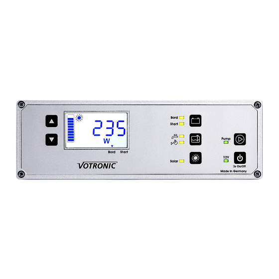
VPC Terra
VOTRONIC Power Control (VPC)
Multi-Panel System for campers, collating the most important functions and information in a user-friendly
manner in one unit.
Voltage board- and starter battery in V
Level indicator
Level fresh- and sewage water tank in %
Solar Computer
Suitable for all VOTRONIC solar charging
controllers since year of production 2014.
Instantaneous solar power in W
Instantaneous solar current in A
Charged solar capacity in Ah
Charged solar power in kWh
Please read the installation instructions, operating manual, and safety instructions page 7
completely prior to starting connection and placing the unit into operation.
The included control cable is specifically designed and tested for this application. It has to be used
necessarily for a proper function of the device. Using a seemingly similar cable can cause malfunction,
which is not covered by guaranty.
Main Switch Function
Main switch for board supply via terminal 1A
Main switch for pump
Main switch for fresh water pump
max. 16 A (potential-free output)
No. 5741
Advertisement
Table of Contents

Related Manuals for Votronic VPC Terra


Summary of Contents for Votronic VPC Terra
- Page 1 Level fresh- and sewage water tank in % Main switch for fresh water pump max. 16 A (potential-free output) Solar Computer Suitable for all VOTRONIC solar charging controllers since year of production 2014. Instantaneous solar power in W Instantaneous solar current in A...
- Page 2 A VOTRONIC tank sensor with continuous output signal is to be installed at the corresponding tank according to the installation instructions. The connections of the tank sensor are to be coupled with the VPC Terra, as indicated in the connection plan. The cross-section of the cables should be min. 0.75 mm². The current supply for the tank sensors by the...
- Page 3 - 3 - Sensor + Starter Battery: The cable allows the voltage measurement at the starter battery and is connected to the positive pole of that battery. The connection cable is to be protected directly at the battery by a 1 to 5 A fuse. The cable cross-section should be 0.75 mm², at least.
- Page 4 - 4 - Operation Control and Display Panel ① The display shows the actual data (level, voltage...) as numerical values. The menu level and the displays of the board battery additionally show a bar graph on the left side. The measurement unit of the displayed value is also shown on the display.
- Page 5 3 seconds until (Set ----) is displayed. Alarm and Battery Protector: The VPC Terra is equipped with an audible alarm device (beeper), which will be activated in case of board battery alarm. An activated alarm is acknowledged by simply pressing any key.
- Page 6 - 6 - Settings Start-up The following settings are to be made for start-up: Board battery disconnection threshold low voltage in V Board battery start threshold in V Activation / Deactivation audible alarm device Solar power (see operation Solar Computer) Access to the Menu The menu for the switching thresholds and alarm device settings is activated by pressing and holding the key "Battery"...
- Page 7 - 7 - Safety Instructions: Safety Regulations and Appropriate Application: The VPC Terra has been designed according to the valid safety regulations. Appropriate application is restricted to: • Control of commercial types of lead storage batteries (acid, gel, AGM), as well as LiFePo4, of the indicated nominal voltage and of connected consumers in fixed installed systems.
- Page 8 1 Pc. Operating Manual Subject to misprints, errors and technical modification without notice. All rights reserved, particularly the right of reproduction. Copyright VOTRONIC 01/2019. Made in Germany by VOTRONIC Elektronik-Systeme GmbH, Johann-Friedrich-Diehm-Str. 10, D-36341 Lauterbach Tel.: +49 (0)6641/91173-0 Fax: +49 (0)6641/91173-20 E-Mail: info@votronic.de Internet: www.votronic.de...
Need help?
Do you have a question about the VPC Terra and is the answer not in the manual?
Questions and answers