Table of Contents
Advertisement
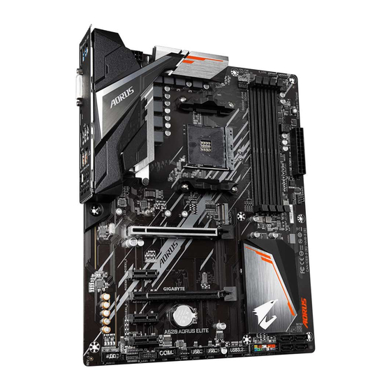
A520 AORUS ELITE
User's Manual
Rev. 1201
For more product details, please visit GIGABYTE's website.
https://www.gigabyte.com/Motherboard/A520-AORUS-ELITE-rev-12?m=ma#kf
GIGABYTE will reduce paper use in order to fulfill the responsibilities of a global citizen.
Also, to reduce the impacts on global warming, the packaging materials of this product
are recyclable and reusable. GIGABYTE works with you to protect the environment.
Advertisement
Table of Contents

Related Manuals for Gigabyte A520 AORUS ELITE


Summary of Contents for Gigabyte A520 AORUS ELITE
- Page 1 For more product details, please visit GIGABYTE's website. https://www.gigabyte.com/Motherboard/A520-AORUS-ELITE-rev-12?m=ma#kf GIGABYTE will reduce paper use in order to fulfill the responsibilities of a global citizen. Also, to reduce the impacts on global warming, the packaging materials of this product are recyclable and reusable. GIGABYTE works with you to protect the environment.
- Page 2 The trademarks mentioned in this manual are legally registered to their respective owners. Disclaimer Information in this manual is protected by copyright laws and is the property of GIGABYTE. Changes to the specifications and features in this manual may be made by GIGABYTE without prior notice.
-
Page 3: Table Of Contents
Table of Contents Chapter 1 Product Introduction ..................4 Motherboard Layout ..................4 Motherboard Block Diagram ................5 Chapter 2 Hardware Installation ..................6 Installation Precautions ..................6 Product Specifications ..................7 Installing the CPU ..................10 Installing the Memory ..................10 Installing an Expansion Card ................. -
Page 4: Chapter 1 Product Introduction
PLUS USB20 USB 2.0 Hub U32_LAN SYS_FAN1 AUDIO M_BIOS PCIEX16 Realtek ® GbE LAN PCIEX1_1 AMD A520 PCIEX2 CODEC PCIEX1_2 ® SATA3 Super I/O PCIEX1_3 A520 AORUS ELITE CLR_CMOS F_AUDIO LED_C1 SYS_FAN3 F_USB1 F_PANEL D_LED1 F_USB2 F_U32 - 4 -... -
Page 5: Motherboard Block Diagram
Motherboard Block Diagram PCI Express 3.0 Bus CPU CLK+/- (100~500 MHz) DDR4 3200/2933/2667/2400/2133 MT/s 1 M.2 Socket 3 AMD Socket HDMI AM4 CPU BIOS DVI-D 1 USB 3.2 Gen 2 Type A 3 USB 3.2 Gen 1 ® Super I/O CODEC 4 SATA 6Gb/s AMD A520... -
Page 6: Chapter 2 Hardware Installation
Chapter 2 Hardware Installation Installation Precautions The motherboard contains numerous delicate electronic circuits and components which can become damaged as a result of electrostatic discharge (ESD). Prior to installation, carefully read the user's manual and follow these procedures: • Prior to installation, make sure the chassis is suitable for the motherboard. •... -
Page 7: Product Specifications
Support for ECC Un-buffered DIMM 1Rx8/2Rx8 memory modules Š Support for non-ECC Un-buffered DIMM 1Rx8/2Rx8/1Rx16 memory modules Š Support for Extreme Memory Profile (XMP) memory modules Š (Go to GIGABYTE's website for the latest supported memory speeds and memory modules.) Onboard Integrated Graphics Processor: Š Graphics 1 x DVI-D port, supporting a maximum resolution of 1920x1200@60 Hz * The DVI-D port does not support D-Sub connection by adapter. - Page 8 CPU: Š 1 x USB 3.2 Gen 2 Type-A port on the back panel 3 x USB 3.2 Gen 1 ports on the back panel Chipset: Š 2 x USB 3.2 Gen 1 ports available through the internal USB header 4 x USB 2.0/1.1 ports available through the internal USB headers Chipset+USB 2.0 Hub: Š...
- Page 9 ATX Form Factor; 30.5cm x 24.4cm Š * GIGABYTE reserves the right to make any changes to the product specifications and product-related information without prior notice. & Please visit GIGABYTE's website for support lists of CPU, memory modules, SSDs, and M.2 devices.
-
Page 10: Installing The Cpu
• Make sure that the motherboard supports the memory. It is recommended that memory of the same capacity, brand, speed, and chips be used. (Go to GIGABYTE's website for the latest supported memory speeds and memory modules.) • Always turn off the computer and unplug the power cord from the power outlet before installing the memory to prevent hardware damage. -
Page 11: Installing An Expansion Card
After installing the HDMI device, make sure to set the default sound playback device to HDMI. (The item name may differ depending on your operating system.) (Note 1) To enable the Q-Flash Plus function, please navigate to the "Unique Features" page of GIGABYTE's website for more information. - Page 12 Mic In/Side Speaker Out You can change the functionality of an audio jack using the audio software. & Please visit GIGABYTE's website for details on configuring the audio software. https://www.gigabyte.com/WebPage/697/realtek897-audio.html • When removing the cable connected to a back panel connector, first remove the cable from your device and then remove it from the motherboard.
-
Page 13: Internal Connectors
Internal Connectors ATX_12V M2A_CPU F_PANEL CPU_FAN F_AUDIO SYS_FAN1/2/3 F_U32 CPU_OPT F_USB1/F_USB2 D_LED1/D_LED2 LED_C1/LED_C2 QFLASH_PLUS CLR_CMOS SATA3 0/1/2/3 Read the following guidelines before connecting external devices: • First make sure your devices are compliant with the connectors you wish to connect. •... - Page 14 1/2) ATX_12V/ATX (2x4 12V Power Connector and 2x12 Main Power Connector) With the use of the power connector, the power supply can supply enough stable power to all the components on the motherboard. Before connecting the power connector, first make sure the power supply is turned off and all devices are properly installed.
- Page 15 LED strip. For how to turn on/off the lights of the LED strip please visit the "Unique Features" webpage of GIGABYTE's website. Before installing the devices, be sure to turn off the devices and your computer. Unplug the power cord from the power outlet to prevent damage to the devices.
- Page 16 1.5Gb/s standard. Each SATA connector supports a single SATA device. The SATA connectors support RAID 0, RAID 1, and RAID 10. Please navigate to the "Configuring a RAID Set" page of GIGABYTE's website for instructions on configuring a RAID array.
- Page 17 Connects to the power switch on the chassis front panel. You may configure the way to turn off your system using the power switch (please navigate to the "BIOS Setup" page of GIGABYTE's website and search for "Settings\Platform Power" for more information).
- Page 18 13) F_U32 (USB 3.2 Gen 1 Header) The header conforms to USB 3.2 Gen 1 and USB 2.0 specification and can provide two USB ports. For purchasing the optional 3.5" front panel that provides two USB 3.2 Gen 1 ports, please contact the local dealer.
- Page 19 • Always turn off your computer before clearing the CMOS values. • After system restart, go to BIOS Setup to load factory defaults (select Load Optimized Defaults) or manually configure the BIOS settings (please navigate to the "BIOS Setup" page of GIGABYTE's website for more information).
-
Page 20: Chapter 3 Bios Setup
If this occurs, try to clear the CMOS values and reset the board to default values. • Refer to the introductions of the battery/clear CMOS jumper in Chapter 2 or navigate to the "BIOS Setup" page of GIGABYTE's website and search for "Load Optimized Defaults" for how to clear the CMOS values. - Page 21 Startup Screen: The following startup Logo screen will appear when the computer boots. Function Keys Function Keys: <DEL>: BIOS SETUP\Q-FLASH Press the <Delete> key to enter BIOS Setup or to access the Q-Flash utility in BIOS Setup. <F12>: BOOT MENU Boot Menu allows you to set the first boot device without entering BIOS Setup.
-
Page 22: Chapter 4 Installing The Operating System And Drivers
Windows installation process. After the operating system is installed, we recommend that you install all required drivers from the GIGABYTE APP Center to ensure system performance and compatibility. If the operating system to be installed requires that you provide additional RAID driver during the OS installation... -
Page 23: Drivers Installation
After you install the operating system, a dialog box will appear on the bottom-right corner of the desktop asking if you want to download and install the drivers and GIGABYTE applications via APP Center. Click Install to proceed with the installation. (In BIOS Setup, make sure Settings\IO Ports\APP Center Download & Install Configuration\APP Center Download & Install is set to Enabled.) -
Page 24: Chapter 5 Appendix
• An Internet connected computer. • A USB thumb drive. An M.2 PCIe SSD cannot be used to set up a RAID set with a SATA hard drive. & Please visit GIGABYTE's website for details on configuring a RAID array. https://www.gigabyte.com/WebPage/543/a520-raid.html - 24 -... -
Page 25: Regulatory Notices
Commission Delegated Directive (EU) 2015/863 Statement Diretiva RSP 2011/65/UE. A conformidade com estas diretivas é verificada GIGABYTE products have not intended to add and safe from hazardous utilizando as normas europeias harmonizadas. substances (Cd, Pb, Hg, Cr+6, PBDE, PBB, DEHP, BBP, DBP and DIBP). -
Page 26: Contact Us
Contact Us GIGA-BYTE TECHNOLOGY CO., LTD. Address: No.6, Baoqiang Rd., Xindian Dist., New Taipei City 231 TEL: +886-2-8912-4000, FAX: +886-2-8912-4005 Tech. and Non-Tech. Support (Sales/Marketing) : https://esupport.gigabyte.com WEB address (English): https://www.gigabyte.com WEB address (Chinese): https://www.gigabyte.com/tw GIGABYTE eSupport • To submit a technical or non-technical (Sales/Marketing) question, please link to: https://esupport.gigabyte.com...
Need help?
Do you have a question about the A520 AORUS ELITE and is the answer not in the manual?
Questions and answers