Advertisement
Quick Links
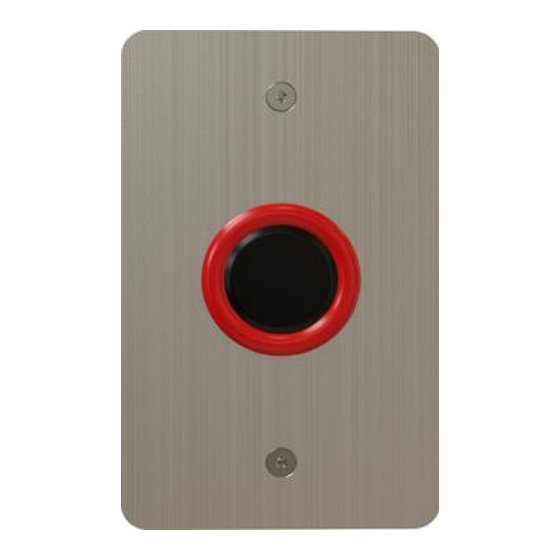
EX-H22N and EX-M22N
Passive Infrared Motion Sensor Switch
Installation Manual
1. Introduction
The EX-H22N and EX-M22N are passive infrared motion sensors (no touch
switch). The new access control switches are designed as flush mounting
for US and UK electric boxes with passive infrared technology. The
switches have a red/green LED ring to display the switch status.
The switches are designed as Request to Exit (REX) buttons for access
control systems, direct activate electric strike, or magnet locks with up to
30 VDC and 1A.
2. Technical Specifications
2.1
Electrical Characteristics
Input Voltage
8–30VDC
Switch Voltage
30VDC [OC]
Maximum Switch Current
1 A
Sense Range
H: 5 to 14 cm
M: 5 to 17 cm
LED Colors
Red/green
2.2
Environmental Characteristics
Operating Environment
Indoor and outdoor use
Operating Temperature Range
-10˚C to 50˚C (14˚F to 122˚F)
Operating Humidity
10% to 90%
Storage Temperature Range
-20˚C to 60˚C (-4˚F to 140˚F)
3. Installation
3.1
Operation Modes
The switches have two operation modes as determined by the brown
wire:
▪
Brown wire not connected – Momentary mode activates the output
[OC]for 1 second
▪
Brown wire connected to GND – Toggle mode activates the output
[OC] ON and OFF
The green wire sets the LED to the initial green color.
3.2
Wiring Information
The switches are wired using a five-wire pigtail as described in Table 1:
Table 1: Wiring
Red
+Vin
Black
Ground (-Vin)
Brown
Mode setting
Green
LED setting
Yellow
Switch output (OC)
To wire the unit:
1. Connect the power supply to the black and red wires.
2. Connect the yellow wire to the REX input in the access control panel
or directly to the lock.
EX-H22N
2.3
Physical Characteristics
Dimensions (W x H x D)
Weight
3.3
Installing the Switch
When selecting the installation area, select a flat wall close to the door or
item that the switch will control. Ensure that there are no iron beams,
door frames, or other obstructions that may prevent insertion of the inlay
in the wall.
To install the switch:
1. Mark the dimensions of the inlay on the wall.
2. Mark two holes for the screws and a hole approximately in the middle
of the plate to insert the wires.
3. Drill the three holes.
4. Mount the unit and tighten the screws.
1
EX-M22N
H: 114 x 70 x 17.8 mm (4.5 x 2.8 x 0.7 in.)
M: 86 x 86 x 17.8 mm (3.4 x 3.4 x 0.7 in.)
H: 193.1 g (6.8 oz)
M: 179.1 g (6.3 oz)
Advertisement

Related Manuals for Rosslare EX-H22N


Summary of Contents for Rosslare EX-H22N
- Page 1 Passive Infrared Motion Sensor Switch Installation Manual 1. Introduction The EX-H22N and EX-M22N are passive infrared motion sensors (no touch switch). The new access control switches are designed as flush mounting for US and UK electric boxes with passive infrared technology. The switches have a red/green LED ring to display the switch status.
- Page 2 The full ROSSLARE Limited Warranty Statement is available in the Quick Links section on the ROSSLARE website at www.rosslaresecurity.com. Rosslare considers any use of this product as agreement to the Warranty Terms even if you do not review them. Contact Information...
Need help?
Do you have a question about the EX-H22N and is the answer not in the manual?
Questions and answers