
Related Manuals for Emcore 5021D-IS

Summary of Contents for Emcore 5021D-IS
- Page 1 System 5000 5021D-IS Wideband Delay Line System with Internal Spool Installation Manual...
-
Page 2: Table Of Contents
Corporation offers a broad portfolio of compound semiconductor-based components and systems for the broadband, fiber optic, satellite communication, defense and solar power markets. EMCORE has two primary operating segments: Fiber Optics and Photovoltaics. The company’s integrated solutions philosophy embodies state-of-the-art technology, material science expertise, and a shared vision of our customer’s goals and objectives to be leaders in fiber... -
Page 3: General
EMI, RFI and lightning. These transmitters and receivers take the best RF design features of Emcore’s extensive families of products and combine them into a compact package compatible with the 10901G Power Supply. -
Page 4: Interface
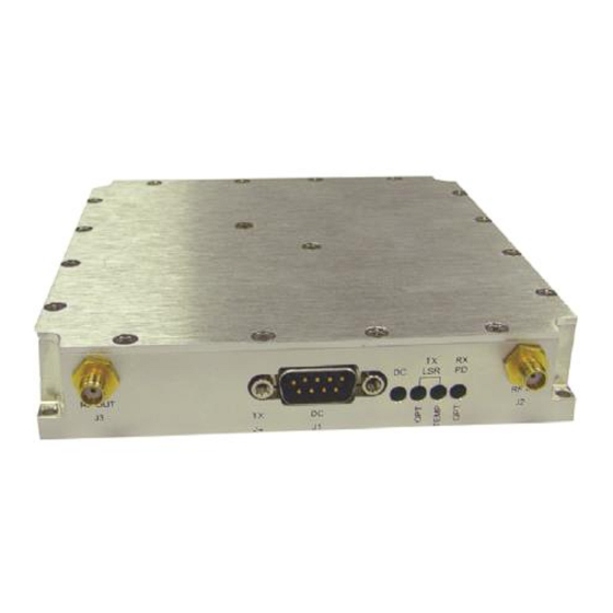
4. Photodiode Optical Power The LED illuminated indicates the photodiode is receiving optical power greater the –12 dBm. 5. RF Input 6. RF output 7. DC Power 8. Mounting Deleted: 11 Deleted: 6 Copyright © 2008 Emcore Corporation MAN-5021D-IS, Rev A Page 4 of... -
Page 5: Installation
Optical power greater than –12 dBm is received. Verify that the delay line has the specified delay and insertion loss, refer to the supplied test data sheet. Deleted: 11 Deleted: 6 Copyright © 2008 Emcore Corporation MAN-5021D-IS, Rev A Page 5 of... -
Page 6: Led Indicator Tables & Diagram
Monitored Values Laser Current 1V/100mA Photodiode Current 1V/1mA Summary Alarm Dry Contact – Sums the Laser Temp, Laser Power and Photodiode Low Optical Power alarms Deleted: 11 Deleted: 6 Copyright © 2008 Emcore Corporation MAN-5021D-IS, Rev A Page 6 of... -
Page 7: Specifications
System 5000 General Certifications CE,CSA,FCC, Operating Temperature -40 to 60C Storage Temperature -40 to 85C Humidity, non-condensing 5 to 95% Dimensions (HxWxD) 1.00” x 5.00” x 5.00” Weight,Typical 1.5 lbs Copyright © 2008 Emcore Corporation MAN-5021D-IS, Rev A Page 7 of 11... -
Page 8: Ordering Information
Ordering Information Model Number Each Emcore product is assigned a unique model number and serial number, which appears on the label of the unit. Model numbers for this series have the form 5021D-X11- ZZZZZZ here; X’ is a one letter designation for the appropriate frequency of the unit, YY’ is a two letter designation the unit overall height and max delay option 11 –... -
Page 9: Optics Handling & Safety
Federal agencies or other authorities of class IIIb lasers must be observed. Do not attempt to modify or to service the laser diode module. Return it to Emcore for service and repair. Contact the Emcore Customer Service Department for a return authorization and further instructions. -
Page 10: Warranty
This warranty is the only warranty made by Emcore and is in lieu of all other warranties, expressed or implied, except as to title, and can be amended only by a written instrument signed by an officer of Emcore. Emcore sales agents or representatives are not authorized to make commitments on warranty returns. - Page 11 FURNISHING OF GOODS, PARTS AND SERVICE HEREUNDER, OR THE PERFORMANCE, USE OF, OR INABILITY TO USE THE GOODS, PARTS AND SERVICE. Emcore will not be responsible for loss of output or reduced output of opto-electronic devices if the customer performs chip mounting, ribbon bonding, wire bonding, fiber coupling, fiber connectorization, or similar operations.