Table of Contents
Advertisement
Quick Links
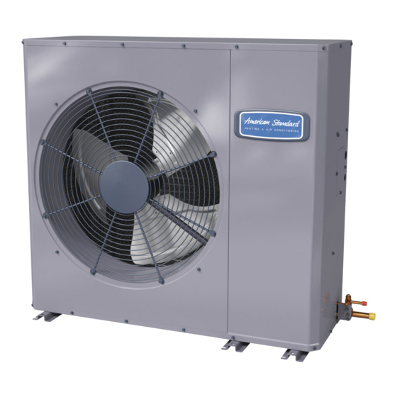
Installation and Operation Manual
Side Discharge AC Models
For coastal applications where units are installed within one (1) mile of salt water, epoxy coated models are recommended. These models
have an 8 week lead time after order.
4A7L6018A1000A
4A7L6024A1000A
4A7L6030A1000A
4A7L6036A1000A
4A7L6042A1000A
4A7L6048A1000A
4A7L6060A1000A
Only qualified personnel should install and service the equipment. The installation, starting up, and servicing of heating, ventilating, and air-conditioning
equipment can be hazardous and requires specific knowledge and training. Improperly installed, adjusted or altered equipment by an unqualified person
could result in death or serious injury. When working on the equipment, observe all precautions in the literature and on the tags, stickers, and labels that
are attached to the equipment.
June 2022
E E p p o o x x y y C C o o a a t t e e d d M M o o d d e e l l
4A7L6018A1COTA
4A7L6024A1COTA
4A7L6030A1COTA
4A7L6036A1COTA
4A7L6042A1COTA
4A7L6048A1COTA
4A7L6060A1COTA
S S A A F F E E T T Y Y W W A A R R N N I I N N G G
1 1 1 1 - - A A C C 4 4 0 0 D D 1 1 - - 1 1 G G - - E E N N
N N o o t t e e : : "Graphics in this document are for representation
only. Actual model may differ in appearance."
Advertisement
Table of Contents

Related Manuals for American Standard 4A7L6018A1000A


Summary of Contents for American Standard 4A7L6018A1000A
- Page 1 8 week lead time after order. E E p p o o x x y y C C o o a a t t e e d d M M o o d d e e l l 4A7L6018A1000A 4A7L6018A1COTA...
- Page 2 . . ©2022 American Standard Heating and Air Conditioning...
-
Page 3: Table Of Contents
Table of Contents Unit Location Considerations ....4 System Start Up ......18 Unit Location Considerations . -
Page 4: Unit Location Considerations
Unit Location Considerations Table 1. Unit Dimensions (in inches) and Weight H x D x W (in) Weight * (lb) Models 4A7L6018A1 36.75 x 14 1/2 x 40 26.75 40.0 36.75 14.5 16.5 17.5 36.75 x 14 1/2 x 40 4A7L6024A1 26.75 40.0... - Page 5 U U n n i i t t L L o o c c a a t t i i o o n n C C o o n n s s i i d d e e r r a a t t i i o o n n s s Table 2.
-
Page 6: Unit Location Considerations
U U n n i i t t L L o o c c a a t t i i o o n n C C o o n n s s i i d d e e r r a a t t i i o o n n s s Unit Location Considerations Table 3. - Page 7 U U n n i i t t L L o o c c a a t t i i o o n n C C o o n n s s i i d d e e r r a a t t i i o o n n s s Table 3.
-
Page 8: Unit Preparation
U U n n i i t t L L o o c c a a t t i i o o n n C C o o n n s s i i d d e e r r a a t t i i o o n n s s Unit Preparation Check for damage and report promptly to the carrier any damage found to the unit. -
Page 9: Refrigerant Line Considerations
U U n n i i t t L L o o c c a a t t i i o o n n C C o o n n s s i i d d e e r r a a t t i i o o n n s s Refrigerant Line Considerations Table 7. - Page 10 U U n n i i t t L L o o c c a a t t i i o o n n C C o o n n s s i i d d e e r r a a t t i i o o n n s s Table 10.
- Page 11 U U n n i i t t L L o o c c a a t t i i o o n n C C o o n n s s i i d d e e r r a a t t i i o o n n s s Table 13.
-
Page 12: Refrigerant Line Brazing
U U n n i i t t L L o o c c a a t t i i o o n n C C o o n n s s i i d d e e r r a a t t i i o o n n s s Refrigerant Line Brazing Table 16. - Page 13 U U n n i i t t L L o o c c a a t t i i o o n n C C o o n n s s i i d d e e r r a a t t i i o o n n s s Table 16.
-
Page 14: Refrigerant Line Leak Check
U U n n i i t t L L o o c c a a t t i i o o n n C C o o n n s s i i d d e e r r a a t t i i o o n n s s Refrigerant Line Leak Check Table 17. -
Page 15: Service Valves
Service Valves Table 18. Open the Gas Service Valve 1/4 Turn Only Important: Leak check and evacuation must be completed before opening the service valves. Counterclockwise Note: Do not vent refrigerant gases into the atmosphere. for Full Open Position Remove valve stem cap. Using a wrench, turn valve stem 1/4 turn counterclockwise to the fully open position. -
Page 16: Communicating
Electrical — Low Voltage Non Communicating Table 20. Low Voltage Maximum Wire Length 24 VOLTS The table defines the maximum total length of low voltage wiring WIRE SIZE MAX. WIRE LENGTH from the outdoor unit, to the indoor unit, and to the thermostat. Note: The use of color coded low voltage wire is recommended to 18 AWG 150 Ft... -
Page 17: Electrical - High Voltage
E E l l e e c c t t r r i i c c a a l l — — L L o o w w V V o o l l t t a a g g e e N N o o n n C C o o m m m m u u n n i i c c a a t t i i n n g g Electrical —... -
Page 18: System Start Up
E E l l e e c c t t r r i i c c a a l l — — L L o o w w V V o o l l t t a a g g e e N N o o n n C C o o m m m m u u n n i i c c a a t t i i n n g g System Start Up Set the system thermostat to OFF. -
Page 19: Subcooling Charging In Cooling Between 55° F And 120° Od
Subcooling Charging in Cooling between 55° F and 120° OD Ambient American Standard has always recommended 4. Measure Liquid Line Temperature and Refrigerant installing American Standard approved matched Pressure at service valves. indoor and outdoor systems. 5. Determine total refrigerant line length, and height (lift) if indoor section is above the condenser. -
Page 20: System Charge Adjustment
System Charge Adjustment Table 24. Temperature Measurements (Systems can be rated with TXV, EEV or Piston. Ensure charging method is correct). Check the outdoor temperatures. 120° F Subcooling using “Charging Mode-Cooling” is the only recommended method of charging between 55 ° F and 120° F ambient outdoor temperature. -
Page 21: Refrigerant Charging Chart
Refrigerant Charging Chart R-410A REFRIGERANT CHARGING CHART DESIGN SUBCOOLING (°F) LIQUID TEMP (°F) LIQUID GAGE PRESSURE (PSI) 11-AC40D1-1G-EN... -
Page 22: Subcool Charging Charts
Subcool Charging Charts Figure 1. 1.5 Ton Models Figure 5. 3.5 Ton Models SUBCOOL CHARGING CHART CORRECTIONS TABLE (FOR LINE LENGTH AND RISE) SUBCOOL CHARGING CHART CORRECTIONS TABLE (FOR LINE LENGTH AND RISE) Add 4° Add 1° 4° Add 1° Add 1°... -
Page 23: Charging The Unit
Charging the Unit Table 26. Stabilize the system Wait 20 minutes for the system condition to stabilize between adjustments. Note: When the Liquid Line Temperature and Gage Pressure 20 MIN. approximately match the chart, the system is properly charged. Remove gauges. Replace service port caps to prevent leaks. - Page 24 C C h h a a r r g g i i n n g g t t h h e e U U n n i i t t Table 29. Proper Gage Pressure Adjust refrigerant level to attain proper gage pressure. Add refrigerant if the Liquid Gage Pressure is lower than the chart value.
-
Page 25: Checkout Procedures
Checkout Procedures The final phase of the installation is the system Checkout Procedures. The following list represents the most common items covered in a Checkout Procedure. Confirm all requirements in this document have been met. ☐ All wiring connections are tight and properly secured. ☐... -
Page 26: Wiring Diagrams
Wiring Diagrams Figure 8. 1.5, 2.0, 2.5, 3.0, 3.5 and 4.0 Ton Models 11-AC40D1-1G-EN... - Page 27 W W i i r r i i n n g g D D i i a a g g r r a a m m s s Figure 9. 1.5, 2.0, 2.5, 3.0, 3.5 and 4.0 Ton Models 11-AC40D1-1G-EN...
- Page 28 W W i i r r i i n n g g D D i i a a g g r r a a m m s s Figure 10. 5.0 Ton Models 11-AC40D1-1G-EN...
- Page 29 W W i i r r i i n n g g D D i i a a g g r r a a m m s s Figure 11. 5.0 Ton Models 11-AC40D1-1G-EN...
-
Page 30: Pressure Curves
Pressure Curves PRESSURE CURVES (Refer below table for models) INDOOR ENTERING WET BULB CURVES TOP TO BOTTOM 71, 67, 63 AND 59 DEG F. Cooling OD Model @SCFM 4A7L6018A1 OUTDOOR TEMPERATURE (Degree F) 4A7L6024A1 INDOOR ENTERING 4A7L6030A1 WET BULB CURVES TOP TO BOTTOM 71, 67, 63 AND 59 DEG F. - Page 31 P P r r e e s s s s u u r r e e C C u u r r v v e e s s PRESSURE CURVES (Refer below table for models) INDOOR ENTERING WET BULB CURVES TOP TO BOTTOM 71, 67, 63 AND 59 DEG F.
- Page 32 P P r r e e s s s s u u r r e e C C u u r r v v e e s s PRESSURE CURVES (Refer below table for models) INDOOR ENTERING WET BULB CURVES TOP TO BOTTOM 71, 67, 63 AND 59 DEG F.
- Page 33 P P r r e e s s s s u u r r e e C C u u r r v v e e s s PRESSURE CURVES (Refer below table for models) INDOOR ENTERING WET BULB CURVES TOP TO BOTTOM 71, 67, 63 AND 59 DEG F.
- Page 34 N N o o t t e e s s 11-AC40D1-1G-EN...
- Page 35 N N o o t t e e s s 11-AC40D1-1G-EN...
- Page 36 About American Standard Heating and Air Conditioning American Standard has been creating comfortable and affordable living environments for more than a century. For more information, please visit www.americanstandardair.com. The AHRI Certified mark indicates company participation in the AHRI Certification program. For verification of individual certified products, go to ahridirectory.org.
Need help?
Do you have a question about the 4A7L6018A1000A and is the answer not in the manual?
Questions and answers