
Subscribe to Our Youtube Channel
Related Manuals for ENMET EX-5185-PID

Summary of Contents for ENMET EX-5185-PID
- Page 1 ENMET Corporation PO Box 979 Ann Arbor, MI 48106-0979 www.enmet.com EX-5185-PID Toxic Gas Sensor/Transmitter Manual Manual Part Number 80003-091 MCN-13-006, 10/24/13...
-
Page 2: Table Of Contents
EX-5185-PID ENMET Corporation Table of Contents 1.0 I ............................... 1 NTRODUCTION 1.1 Unpack ....................................1 1.2 Check Order ..................................1 1.3 Serial Numbers................................... 1 2.0 F EX-5185 ........................... 2 EATURES OF THE 3.0 I EX-5185 ..........................3 NSTALLATION OF THE 3.1 Mounting the EX-5185 Enclosure ............................. -
Page 3: Introduction
Photoionization detector (PID) sensor. The EX-5185 is meant to be used in conjunction with an appropriate power supply and controller. The ENMET EX-5185 sensor/transmitter has been designed and approved to be used in a Class I, Div. 1, Groups B, C, D, classified areas. The approval was issued by CSA International. -
Page 4: Features Of The Ex-5185
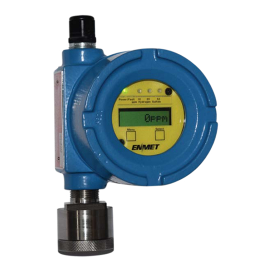
EX-5185-PID ENMET Corporation 2.0 Features of the EX-5185 See Figure 1 for location of features: Feature Description Display LCD: Indicates the level of gas detected by sensor Gain Potentiometer POT 1: Display contrast adjustment POT 2: Does Not apply to PID, not used Do not adjust... -
Page 5: Installation Of The Ex-5185
, 4-20 mA S/T for the detection of toxic gas. The S/T is meant to be used in conjunction with an appropriate power supply and controller. The ENMET EX-5185 sensor/transmitter has been designed and approved to be used in a Class I, Div. 1, Groups B, C, D, classified areas. The approval was issued by CSA International. -
Page 6: Wiring The Ex-5185 To A Control Unit
ONTROLLER IRING To J4 Position Function 24 V power 4 - 20 mA out RS-485 D+ P l u g J 4 Wires to RS-485 D– Controller *Contact ENMET for Modbus address information 1 2 3 Circuit Board Bottom View... - Page 7 EX-5185-PID ENMET Corporation Display Overlay Screws (2 places) Display Overlay Display Display Overlay Standoffs Magnetic Switches (2 places) (2 places) Printed Circuit Board (PCB) J4 and J8 Terminals are located on the bottom side of PCB Sensor/Transmitter Enclosure Cutaway View...
-
Page 8: Operation Of The Ex-5185
EX-5185-PID ENMET Corporation 4.0 Operation of the EX-5185 It is best to have the EX-5185 transmitters powered up and operational for 24 hours before applying calibration or test gas to them. When the EX-5185 transmitter is first powered up, it goes through a series of momentary screens, which identify the instrument model number, serial number and software revision. -
Page 9: Normal Display Mode
EX-5185-PID ENMET Corporation 4.2 Normal Display Mode When the EX-5185 is installed as described in section 3, and in clean air, the POWER green LED is on, the display is lit and the information on the display is measurement of the target gas detected by the EX-5185. The red alarm and fault LEDs are not lit. -
Page 10: Maintenance Of The Ex-5185
EX-5185-PID ENMET Corporation 5.0 Maintenance of the EX-5185 Do not open the in a classified area. EX-5185 S/T AUTION : Do Not Attempt A Span Procedure Without Calibration Gas Applied to The Sensor ; if this is done, the S/T is forced AUTION into a calibration fault mode. -
Page 11: Calibration Of The Ex-5185
Calibration Zero and Span functions are two separate procedures. They operate independently of each other. It is recommended that the Zero procedure be done prior to the Span procedure. ENMET Corporation recommends at least quarterly calibration of the EX-5185 transmitters. - Page 12 : EX-5185 alarm points are independent of a controller. When a controller is supplied by ENMET Corporation the alarm points for the EX-5185 and the controller have been set accordingly. See the manual of the controller the EX-5185 sensor transmitter has been connected to for proper adjustment of the alarm points of the controller with the EX-5185 sensor transmitter.
-
Page 13: Zero Adjust
EX-5185-PID ENMET Corporation 5.2.1 Zero Adjust A ZERO function should be performed only when the EX-5185 sensor/transmitter is exposed to fresh air. If the air at the sensor is in question, use a cylinder of 20.9% oxygen to provide a clean air reference. Attach the cylinder to the calibration adapter, fill the humidifier bowl halfway with water and allow gas to flow over the sensor for 3 –... - Page 14 ELECT If the Zero signal is within Preset Specs the EX-5185-PID will display Cal OK, See Section 5.2.1 If the Zero signal is not within Preset Specs the EX-5185-PID will display Bad ZERO Bad ZERO : Some software revisions require the S...
-
Page 15: Heater Voltage Settings
Heater Voltages are necessary for PID sensors. They are preset at the factory and should not require field adjustment. Do not adjust these voltages unless specifically instructed to do so by ENMET Corporation Technical Support Staff. : Improper adjustment of heater voltages can damage sensors voiding any warranties and also alter the operating AUTION characteristics of the sensor in such a way that the EX-5185 may not respond to it’s target gas. -
Page 16: Replacement Part Numbers
ENMET shall not be liable for any loss or damage caused by the improper use of the product. The purchaser indemnifies and saves harmless the company with respect to any loss or damages that may arise through the use by the purchaser or others of this equipment. - Page 17 Fax 734.761.3220 Returning an Instrument for Repair ENMET instruments may be returned to the factory or any one of our Field Service Centers for regular repair service or calibration. The ENMET Repair Department and Field Service Centers also perform warranty service work.
- Page 18 K UPS Account number: ________________________ K Federal Express: K Ground K Express Saver K P-1 K Standard K 2-Day Air K FedEx Account number: ________________________ Would you like ENMET to insure the return shipment? K No K Yes Insurance Amount: $_________________...
Need help?
Do you have a question about the EX-5185-PID and is the answer not in the manual?
Questions and answers