Advertisement
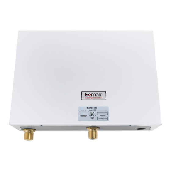
THREE PHASE THERMOSTATIC
ELECTRIC INSTANTANEOUS WATER HEATER
MODELS: EX320T3, EX320T2T, EX240T3, EX240T2T
EX180T3, EX180T2T (277 volts)
INSTALLATION GUIDE AND OWNERS MANUAL
BEFORE ATTEMPTING INSTALLATION OF THIS UNIT OR MAKING ANY ADJUSTMENTS
TO THE UNIT ALWAYS BE SURE MAIN CIRCUIT BREAKER IS OFF TO PREVENT DANGER
PLEASE TAKE THE TIME TO READ NOT ONLY THIS MANUAL BUT ALSO THE
WARRANTY CARD ENCLOSED. WARRANTY OF THIS HEATER WILL DEPEND ON PROPER
INSTALLATION AND OPERATION. THE WARRANTY SHALL BE VOID IF THE DESIGN OR
STRUCTURE OF THE WATER HEATER HAS BEEN ALTERED IN ANY WAY WHATSOEVER. THE
MANUFACTURER OF THIS WATER HEATER WILL NOT BE LIABLE FOR ANY DAMAGES
BECAUSE OF FAILURE TO COMPLY WITH THE INSTALLATION AND OPERATING
INSTRUCTIONS OUTLINED ON THE FOLLOWING PAGES.
IF YOU REQUIRE ANY HELP OR HAVE ANY QUESTIONS RELATING TO THE
INSTALLATION OR PERFORMANCE OF THIS HEATER, PLEASE CALL OUR TECHNICAL
SERVICE DEPARTMENT TOLL-FREE:
HAVE THE INFORMATION LISTED BELOW BEFORE BEFORE CALLING.
MODEL :
SERIAL NO :
INSTALLATION DATE :
ema
E
OF SERIOUS ELECTRIC SHOCK.
INSTALLER/ CONSUMER RESPONSIBILITIES
1-800-543-6163
Eemax Inc., 353 Christian ST., Oxford, CT 06478
X
WARNING
ELEMENT RESISTANCE:
SWITCH ON FLOW RATE:
OPERATING TEMPERATURE
MIN
1
OHMS
GPM
MAX
Advertisement
Table of Contents

Summary of Contents for EemaX EX320T3
- Page 1 INSTALLATION OR PERFORMANCE OF THIS HEATER, PLEASE CALL OUR TECHNICAL SERVICE DEPARTMENT TOLL-FREE: 1-800-543-6163 HAVE THE INFORMATION LISTED BELOW BEFORE BEFORE CALLING. MODEL : ELEMENT RESISTANCE: OHMS SERIAL NO : SWITCH ON FLOW RATE: OPERATING TEMPERATURE INSTALLATION DATE : Eemax Inc., 353 Christian ST., Oxford, CT 06478...
- Page 2 GENERAL The Eemax “Three Phase Thermostatic” water heater is specifically designed to take in cold or pre-heated water and heat it to temperatures suitable for commercial washing, sluicing or processing up to a maximum temperature of 180 F (82 deg. C). To obtain optimum performance and energy savings, the unit should be located as near as possible to the point of use.
-
Page 3: Mounting The Unit
MOUNTING THE UNIT 1) The unit should be mounted as close to the point of use as possible. 2) This unit must only be mounted in the vertical position with the water fittings located at the bottom of the unit. Mounting other than in the vertical position WILL cause element burn out. 3) The cold water inlet is on the right hand side and the hot water outlet is on the left hand side. -
Page 4: Plumbing Hook-Up
PLUMBING HOOK-UP 1) The unit is supplied with compression fittings, USE THESE; DO NOT USE TAPERED THREADED PIPE FITTINGS AND DO NOT SOLDER PIPE TO THE INLET OR OUTLET. 2) Take care to ensure that the pipes are correctly aligned with the inlet and outlet bosses in order to avoid excessive stress on the heater body molding. -
Page 5: Electrical Hook-Up
ELECTRICAL HOOK-UP WARNING HAZARD OF ELECTRICAL SHOCK! BEFORE BEGINNING ANY WORK ON THE INSTALLATION, MAKE SURE THE ELECTRICAL SUPPLY TO THE HEATER IS TURNED “OFF”. FAILURE TO DO THIS COULD RESULT IN DEATH, SERIOUS BODILY INJURY, OR PROPERTY DAMAGE. WARNING WATER HEATERS EQUIPPED FOR ONE VOLTAGE ONLY: CHECK THE RATING PLATE ON THE FRONT OF THE UNIT. - Page 6 COMMISSIONING YOUR HEATER IMPORTANT Before switching “on” the power at the main circuit breaker panel make sure that the hot water circuit is free of air pockets or premature failure of the heating element will occur. To do this open all hot water faucets one at a time for a minute or two until the water flow is continuous and free from “gulping”...
- Page 7 the desired temperature and that all three elements are pulsing equally. The thermostats are now set and the water temperature will always be the same when the lights are pulsing. 7) Check performance of flow switch by opening and closing the faucet of the outlet valve a few times.
-
Page 8: Troubleshooting
TROUBLESHOOTING SYMPTOM: NO HEAT INDICATOR LIGHT OFF 1)ELECTRIC SUPPLY IS OFF Turn on the main circuit breaker. 2)NO OR LOW WATER FLOW Ensure that the minimum flow rate to switch on your heater is met, for this figure refer to the front cover of this manual. Also check that the inlet filter screen is clear from any debris. -
Page 9: Replacement Parts Diagram
REPLACEMENT PARTS DIAGRAM HEATER CORE ASSEMBLY FOR EX180 T3 PART# EX1280 FOR EX240 T3 PART# EX960 FOR EX320 T3 PART# EX720 FOR ELEMENT ( PLEASE QUOTE POWER AND VOLTAGE REQUIREMENTS WHEN ORDERING) TRIAC PART# EX18 L1 L2 L3 THERMOSTATIC For supply connections use 8 AWG or larger wires suitable for at least 75 c (167F) PART# EX100 THIS APPLIANCE MUST BE GROUNDED...


Need help?
Do you have a question about the EX320T3 and is the answer not in the manual?
Questions and answers