Table of Contents
Advertisement
Quick Links
Advertisement
Table of Contents

Related Manuals for Agito AGA1 Series


Summary of Contents for Agito AGA1 Series
- Page 1 AGA1xx Central-i DC Power Amplifier Product Manual...
- Page 2 Agito Akribis Systems Ltd. Products Rights AGDx, AGCx, AGMx, AGAx, AGIx, and AGLx are products designed by Agito Akribis Systems Ltd. in Israel. Sales of the products are licensed to Akribis Systems Pte Ltd. under intercompany license agreement.
-
Page 3: Table Of Contents
Contents Product Description _____________________________________________________ 5 General Description ______________________________________________________________ 5 Part Numbering _________________________________________________________________ 6 1.2.1 AGA110 Product Variants ___________________________________________________ 6 1.2.2 AGA101 Product Variants ___________________________________________________ 6 1.2.3 AGA102 Product Variants ___________________________________________________ 7 1.2.4 AGA103 Product Variants ___________________________________________________ 7 System Design ___________________________________________________________________ 8 Technical Specifications __________________________________________________________ 10 Environmental Specifications ______________________________________________________ 16 Safety _______________________________________________________________ 17... - Page 4 Electrical Interfaces Circuitry ______________________________________________________ 60 3.8.1 Isolated Digital Inputs _____________________________________________________ 60 3.8.2 Isolated Digital Outputs ___________________________________________________ 61 3.8.3 Analog Input ____________________________________________________________ 62 3.8.4 Differential Inputs ________________________________________________________ 62 3.8.5 Differential Outputs ______________________________________________________ 63 3.8.6 Bi-directional Differential I/Os ______________________________________________ 63 3.8.7 Hall Sensors _____________________________________________________________ 64 Operation ____________________________________________________________ 65 Motor Configuration _____________________________________________________________ 65 Drive/Motor Overload Protection __________________________________________________ 68...
-
Page 5: Product Description
General Description Product Description 1.1 General Description The AGA1xx is a series of DC amplifiers controlled by an AGM series Central-i master. The master controller reads encoder values and current samples from the amplifiers, performs control loops calculation, and generates PWM commands for the amplifiers. Communication between AGA1xx amplifiers and master controller is through a fast Central-i fieldbus, which supports 16 kHz sample rate motion profiler and all servo loops. -
Page 6: Part Numbering
Part Numbering 1.2 Part Numbering 1.2.1 AGA110 Product Variants Product Description Part Number Format Remote amplifier AGA110-CI-5Dxx CI: Central-i communication 5D: 80–190 VDC power supply xx: Continuous and peak current options 01: 1.4 Arms continuous, 2.8 Arms peak 02: 2.8 Arms continuous, 5.6 Arms peak ... -
Page 7: Aga102 Product Variants
Part Numbering 1.2.3 AGA102 Product Variants Product Description Part Number Format Amplifier AGA102-CI-1Dxx CI: Central-i communication 1D: 12—48 VDC power supply xx: Continuous and peak current options 01: 1.4 A continuous, 2.8 A peak 02: 2.8 A continuous, 5.6 A peak ... -
Page 8: System Design
System Design 1.3 System Design Figure 2. AGA110 system connections and wiring Figure 3. AGA101 system connections and wiring AGA1xx Product Manual Rev.2.0 Page 8... - Page 9 System Design Figure 4. AGA102 system connections and wiring Figure 5. AGA103 system connections and wiring AGA1xx Product Manual Rev.2.0 Page 9...
-
Page 10: Technical Specifications
Technical Specifications 1.4 Technical Specifications Electrical/Mechanical Specifications Feature AGA110 AGA101 AGA102 AGA103 Number of axes Power supply 80–190 VDC 12–90 VDC 12–48 VDC 12–48 VDC Continuous output current 1.4 | 2.8 | 5.6 | 1.4 | 2.8 | 5.6 1.4 | 2.8 | 5.6 (internally limited by firmware) 7.0 A Peak output current... - Page 11 Technical Specifications Encoder Ports Specifications Feature Specification Encoder types Incremental AqB, Sin/Cos Absolute: EnDat 2.2, BiSS-C Power supply to encoder AGA110: 0.5A per encoder port AGA101: 0.5A per encoder port AGA102: 0.5A per encoder port AGA103: 0.3A per encoder port Max.
- Page 12 Technical Specifications I/O Specifications Feature Specification Power supply for optically isolated Voltage: 5–28 VDC I/Os Optically isolated digital inputs Type: PNP/NPN Propagation delay: 10 µs Max. frequency: 100 kHz Functionality: limit switches, home, captures, start motion, gain scheduling, and others Optically isolated digital outputs Type: PNP/NPN Max current: 0.5A (for NPN type), 0.3A (for PNP type)
- Page 13 Technical Specifications AGA110 Dimensions and Weight Feature Specification Unit dimensions (max) H=162 mm, W=36.50 mm, D=102 mm Package dimensions H=210 mm x W=50 mm x D=140 mm Unit weight 306 g Shipping weight 410 g Figure 6. AGA110 dimensions (mm) AGA1xx Product Manual Rev.2.0 Page 13...
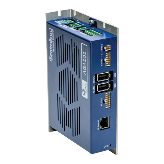
- Page 14 Technical Specifications AGA101 Dimensions and Weight Feature Specification Unit dimensions (max) H=162 mm, W=36.50 mm, D=102 mm Package dimensions H=210 mm x W=50 mm x D=140 mm Unit weight 306 g Shipping weight 410 g Figure 7. AGA101 dimensions (mm) AGA1xx Product Manual Rev.2.0 Page 14...
- Page 15 Technical Specifications AGA102 Dimensions and Weight – AGA102 Feature Specification Unit dimensions (max) H=120 mm, W=33 mm, D=82 mm Package dimensions H=170 mm x W=50 mm x D=120 mm Unit weight 200 g Shipping weight 286 g Figure 8. AGA102 dimensions (mm) AGA1xx Product Manual Rev.2.0 Page 15...
-
Page 16: Environmental Specifications
Environmental Specifications AGA103 Dimensions and Weight Feature Specification Unit dimensions (max) H=80 mm, W=35 mm, D=60 mm Package dimensions H=170 mm x W=50 mm x D=120 mm Unit weight 118 g Shipping weight 204 g Figure 9. AGA103 Dimensions (mm) 1.5 Environmental Specifications The operational range may be additionally limited by the internal temperature protection of the product. -
Page 17: Safety
Safety Symbols Safety 2.1 Safety Symbols Safety symbols indicate a potential for personal injury or equipment damage if the prescribed precautions and safe operating practices are not followed. The following safety symbols are used in the product documentation. Safety Symbols Symbol Meaning Description... -
Page 18: Compliance
Compliance Warning Capacitors on the DC bus can retain hazardous voltages after input power has been removed. Attention Do not attempt to hinder or override the product’s or system’s fault detection or protection circuits. You must determine the cause of a fault and correct it before you attempt to operate the system. -
Page 19: Installation
Unpacking and Packing Installation 3.1 Unpacking and Packing Save the original box and packing materials in case you need to pack and return the product to the manufacturer. To unpack the product: 1. Carefully remove the product from the box and the packing materials. 2. -
Page 20: Mounting Multiple Power Amplifiers
Mounting 3.2.2 Mounting Multiple Power Amplifiers When mounting multiple amplifiers within a cabinet, clearance between units must be at least 5 mm. In addition, top and bottom clearance must be at least 50 mm. Ambient temperature in the cabinet must not exceed limit defined in the section Environmental Specifications. -
Page 21: Electrical Installation
Electrical Installation 3.3 Electrical Installation 3.3.1 Power Supplies Several power sources are required for AGA1xx operation when the amplifier is connected to external devices. The power sources provide power to the motor and brake, and to logic and I/Os circuits. Power Source Description AGA110 AGA101... -
Page 22: Grounding
Electrical Installation Regeneration voltage threshold parameters are software configurable and can be modified according to the motor’s maximum voltage specification. Warning DC Vbus is monitored, and motors will be disabled if voltage is too high. However, there is no protection against the connection of an excessive voltage power supply that will damage the product. - Page 23 Electrical Installation Ground Domains Name Ground Domain Notes DC power input GND (I/O return) External DC power supply Central-i communication General Isolated for Central-i remote devices Isolated digital inputs/outputs General Isolated Differential inputs/outputs (not isolated) GND Analog inputs/outputs (not isolated) Brake control output General External DC power supply...
-
Page 24: Communication - Central-I
Communication – Central-i 3.4 Communication – Central-i The AGA1xx amplifiers use Central-i for communication with a centralized controller module. The Central-i motion control platform includes a multi-axis motion controller, distributed amplifiers and sensors, and control software. The master controller performs all the control functions, including trajectory and position, velocity, and current loops. -
Page 25: Aga110 And Aga101 - Electrical Interfaces
AGA110 and AGA101 – Electrical Interfaces 3.5 AGA110 and AGA101 – Electrical Interfaces 3.5.1 Interface X2: Main Power The amplifier includes protection to prevent damage if polarity is inverted at the power input. Note – Optional scheme for isolated power supplies The amplifier can support fully isolated power supplies, one for the power circuitry to drive the motor, and one for the digital logic. - Page 26 AGA110 and AGA101 – Electrical Interfaces AGA101 Connector X2 is used to supply 12–90 VDC to the AGA101. Figure 14. AGA101 Power connector Connector X2: MAIN PWR Pin # Name Description Main power Power input: 12–90V, up to 8A continuous Power GND Ground –...
-
Page 27: Interface X5: Safety
AGA110 and AGA101 – Electrical Interfaces 3.5.2 Interface X5: Safety Connector X5 is used for the hardware safety function that disables power to the motor. Figure 15. AGA110 Safety connector Figure 16. AGA101 Safety connector Connector X5: SAFETY Pin # Name Description 5V supply for safety circuits Safety_Feedback-... - Page 28 AGA110 and AGA101 – Electrical Interfaces Note – Safety Bypass To bypass the safety circuit on the AGA110/AGA101, do the following on connector X5: Connect pin 1 to both pin 7 and pin 8. Connect pin 5 to both pin 3 and pin 4. ...
-
Page 29: Interface X1: I/O And Backup Power
AGA110 and AGA101 – Electrical Interfaces 3.5.3 Interface X1: I/O and Backup Power Connector X1 has two functions. It supplies DC power supply to the isolated I/Os. Optionally, it provides backup power for the logic components. The amplifier includes protection to prevent damage if polarity is inverted at the power input. Figure 18.AGA110 I/O and backup power connector Figure 19.AGA101 I/O and backup power connector Connector X1: I/O PWR... -
Page 30: Interface X4: Motor
AGA110 and AGA101 – Electrical Interfaces 3.5.4 Interface X4: Motor Connector X4 serves to supply power to the motor, which can be a 3-phase brushless motor, a single phase brushed motor or a voice coil motor, or a stepper motor. Note –... - Page 31 AGA110 and AGA101 – Electrical Interfaces AGA101 Figure 21. AGA101 Motor connector Connector X4: MOTOR Pin # Label Brushless Motor Brushed or Voice Coil Motor Stepper Motor Motor phase A Motor phase + Motor phase 1+ Motor phase B Motor phase - Motor phase 2+ Motor phase C Not connected...
-
Page 32: Interface X3: Regeneration
AGA110 and AGA101 – Electrical Interfaces 3.5.5 Interface X3: Regeneration Connector X3 is used to connect an external power resistor to dissipate energy generated by the motor, typically during deceleration. The motor-generated energy will charge up the internal capacitor. When the internal capacitor is fully charged, the bus voltage will increase. When bus voltage is higher than the operating limit of the product, it will trigger over-voltage protection and disable the motor. -
Page 33: Interface X11: Brake
AGA110 and AGA101 – Electrical Interfaces 3.5.6 Interface X11: Brake Some motors may have a static brake, which is engaged when the motor is not enabled. Connector X11 is used for this functionality. Figure 24. Brake connector Connector X11: BRAKE Pin # Name Description Static brake output for motor. -
Page 34: Interfaces X8 And X9: Encoders
AGA110 and AGA101 – Electrical Interfaces 3.5.7 Interfaces X8 and X9: Encoders X8 and X9 are identical connectors. Each one serves as an interface to a single encoder. Typically, X8 is used for the motor encoder. X9 is used for the secondary feedback device in a dual- loop control system. - Page 35 AGA110 and AGA101 – Electrical Interfaces Mating connector SUNCHU SC-10-4P Wiring 26 AWG, insulation rated for 100V Note – Incremental encoder interface Each differential-pair includes a built-in 120Ω terminator and the required hardware circuits to detect a disconnected encoder cable. When a disconnected encoder cable is detected, the controller will disable the motor.
-
Page 36: Interfaces X7, X10 And X12: I/Os
AGA110 and AGA101 – Electrical Interfaces 3.5.8 Interfaces X7, X10 and X12: I/Os Connectors X7, X10 and X12 are used for connecting external I/O devices to the amplifier. For schematics and more information about these interfaces, refer to the section Electrical Interfaces Circuit. - Page 37 AGA110 and AGA101 – Electrical Interfaces Software Pin # Name Description Representation Digital_Input_7 DInPort.bit(6) Isolated digital input 7 (NPN or PNP, depending on the connection of the group’s common pin). Digital_Input_5 DInPort.bit(4) Isolated digital input 5 (NPN or PNP, depending on the connection of the group’s common pin).
- Page 38 AGA110 and AGA101 – Electrical Interfaces Interface X10 Figure 29. I/O-1 connector Connector: X10: I/O-1 Pin # Name Software Description Representation Vin_24V_IO_RTN I/O power return Vin_24V_IO 24V I/O power Digital_Input_4 DInPort.bit(3) Isolated digital input 4 (NPN or PNP, depending on the connection of the group’s common pin). Isolated digital input 2 (NPN or PNP, depending Digital_Input_2 DInPort.bit(1)
- Page 39 AGA110 and AGA101 – Electrical Interfaces Interface X12 Figure 30. AGA110 I/O-3 connector Figure 31.AGA101 I/O-3 connector Connector X12: I/O-3 Pin # Name Software Description Representation Vin_24V_IO_RTN I/O power return Vin_24V_IO 24V I/O power Digital_Input_11 DInPort.bit(10) Isolated digital input 11 (NPN or PNP, depending on the connection of the group’s common pin) Digital_Input_9 DInPort.bit(8)
- Page 40 AGA110 and AGA101 – Electrical Interfaces Software Pin # Name Description Representation Digital_Input_8 DInPort.bit(7) Isolated digital input 8 (NPN or PNP, depending on the connection of the group’s common pin) Analog_Input_ Analog input 2 return. Return_2 Not connected internally to GND. Mating connector Samtec Inc.
-
Page 41: Interface X6: Central-I
AGA110 and AGA101 – Electrical Interfaces 3.5.9 Interface X6: Central-i Connector X5 is used for communication with the Central-i master controller, such as the AGM800, and other remote amplifiers and devices. Figure 32. Communication connector (Central-i) Connector X6: Central-i (RJ45) Pin # Name Description Central-i data0+... -
Page 42: Aga102 - Electrical Interfaces
AGA102 – Electrical Interfaces 3.6 AGA102 – Electrical Interfaces 3.6.1 Interface X2: Main Power Connector X2 is used to supply 12–48 VDC to the AGA102. The input voltage is connected directly to the amplifier power bridge to drive the axis motor. The input voltage also supplies the power for the amplifier internal logic. -
Page 43: Interface X4: Safety
AGA102 – Electrical Interfaces 3.6.2 Interface X4: Safety Connector X4 is used for the hardware safety function that disables power to the motor. Figure 34. Safety connector Connector X4: SAFETY Pin # Name Description 5V supply for safety circuits Safety_feedback- Safety_feedback negative (emitter) output Safety_input_2- Safety_input_2 negative input... - Page 44 AGA102 – Electrical Interfaces Safety connector circuit diagram Figure 35. Electrical interfaces – safety connector Safety_Input_1 and Safety_Input_2 function independently, thus providing safety redundancy. Each one can disable the power to the motor. Both Safety_Input_1 and Safety_Input_2 disable the power to the motor through hardware ...
-
Page 45: Interface X1: I/O And Backup Power
AGA102 – Electrical Interfaces 3.6.3 Interface X1: I/O and Backup Power Connector X1 has two functions. It supplies DC power supply to the isolated I/Os. Optionally, it provides backup power for the logic components. The amplifier includes protection to prevent damage if polarity is inverted at the power input. Figure 36. -
Page 46: Interface X3: Motor
AGA102 – Electrical Interfaces 3.6.4 Interface X3: Motor Connector X3 serves to supply power to the motor, which can be a 3-phase brushless motor, a single phase brushed motor, a voice coil motor, or a stepper motor. Figure 37. Motor connector Connector X3: MOTOR Pin # Label Brushless Motor Brushed or Voice Coil Motor... -
Page 47: Interface X6: Encoder
AGA102 – Electrical Interfaces 3.6.5 Interface X6: Encoder Connector X6 serves as an interface to a single encoder. Figure 38. Encoder connector Connectors X6: ENC Pin # Name Encoder Types Description AqB Sin/Cos BiSS-C EnDat 2.2 5V power supply. Limited to 0.5A. 5V return and reference for differential signals Encoder_1+ Clock+ Clock+... -
Page 48: Interfaces X7 And X8: I/Os
AGA102 – Electrical Interfaces 3.6.6 Interfaces X7 and X8: I/Os Connectors X7 and X8 are used for connecting external I/O devices to the amplifier. For schematics and more information about these interfaces, refer to the section Electrical Interfaces Circuit. Interface X7 Figure 39. - Page 49 AGA102 – Electrical Interfaces Software Pin # Name Description Representation 5V supply for external I/O circuits. Limited to 0.5A. Digital_Output_2 DOutnPort.bit(1) Isolated digital output 2, programmable sink or source Digital_Output_1 DOutnPort.bit(0) Isolated digital output 1, programmable sink or source Digital_Input_6 DInPort.bit(5) Isolated digital input 6 (NPN or PNP, depending on the connection of the group’s...
- Page 50 AGA102 – Electrical Interfaces Interface X8 Figure 40. I/O-1 connector Connector X8: I/O-1 Pin # Name Software Description Representation 5V_SW1 5V supply for external I/O circuits. Limited to 0.5A Isolated digital input 2 (NPN or PNP, Digital_Input_2 DinPort.bit(1) depending on the connection of the group’s common pin) Digital_Input_Common (1 24V I/O power...
-
Page 51: Interface J5: Central-I
AGA102 – Electrical Interfaces 3.6.7 Interface J5: Central-i Connector X5 is used for communication with the Central-i master controller, such as the AGM800, and other remote amplifiers and devices. Figure 41. Communication connector (Central-i) Connector: Central-i (RJ45) Pin # Name Description Central-i data0+ Bi-directional + data +... -
Page 52: Aga103 - Electrical Interfaces
AGA103 – Electrical Interfaces 3.7 AGA103 – Electrical Interfaces 3.7.1 Interface X5: Main Power Connector X2 is used to supply 12–48 VDC to the AGA103. The input voltage is connected directly to the amplifier power bridge. The input voltage drive the axis motor. It also supplies the power for the amplifier internal logic. -
Page 53: Interface X4: Safety
AGA103 – Electrical Interfaces 3.7.2 Interface X4: Safety Connector X4 is used for the hardware safety function that disables power to the motor. Figure 43. Safety connector Connector X4: SAFETY Pin # Name Description Safety 5V 5V supply for safety circuits Safety Input + Safety_Input positive input Safety Input -... - Page 54 AGA103 – Electrical Interfaces Safety connector circuit diagram Figure 44. Electrical interfaces – safety connector Safety_Input disables the power to the motor through hardware circuitry, without any software intervention. Safety_Input is defined with a positive pin (+) and a negative pin (-). However, the opto-coupler ...
-
Page 55: Interface X3: Motor
AGA103 – Electrical Interfaces 3.7.3 Interface X3: Motor Connector X3 serves to supply power to the motor, which can be a 3-phase brushless motor, a single phase brushed motor, a voice coil motor, or a stepper motor. Figure 45. Motor connector Connector X3: MOTOR Pin # Name Brushless Motor Brushed or Voice Coil Motor... -
Page 56: Interface X2: Encoder
AGA103 – Electrical Interfaces 3.7.4 Interface X2: Encoder Connector X2 serves as an interface to a single encoder. Figure 46. Encoder connector Connector X2: ENC Pin # Name Encoder Type Description AqB Sin/Cos BiSS-C EnDat 2.2 5V power supply. Limited to 0.3A. Encoder_1+ Clock+ Clock+ Clock+ pin for absolute encoders... -
Page 57: Interface X1: I/Os
DInPort.bit(0) Isolated digital input 1 (NPN or PNP, depending on the connection of the group’s common pin). To use as Hall input, go to the Agito PCSuite Digital Input page, and configure as Hall A. AGA1xx Product Manual Rev.2.0 Page 57... - Page 58 AGA103 – Electrical Interfaces Software Pin # Name Description Representation Digital_Input_Common (1 to 2) Common pin (power or return, depending on external connection) for digital input 1 to 2 Digital_Output_1 DOutPort.bit(0) Isolated digital output 1, programmable sink or source Digital_Output_2 DOutPort.bit(1) Isolated digital output 2, programmable sink or source...
-
Page 59: Interface X13: Central-I
AGA103 – Electrical Interfaces 3.7.6 Interface X13: Central-i Connector X5 is used for communication with the Central-i master controller, such as the AGM800, and other remote amplifiers and devices. Figure 48. Communication connector (Central-i) Connector X13: Central-i (RJ45) Pin # Name Description Central-i data0+... -
Page 60: Electrical Interfaces Circuitry
Electrical Interfaces Circuitry 3.8 Electrical Interfaces Circuitry 3.8.1 Isolated Digital Inputs Figure 49. Isolated digital inputs Isolated digital inputs are organized as groups with a dedicated common pin. This enables connection to different voltage supplies. Each group is fully isolated and independent of the other groups. -
Page 61: Isolated Digital Outputs
Electrical Interfaces Circuitry 3.8.2 Isolated Digital Outputs Figure 50. Isolated digital outputs – AGA110, AGA101 and AGA102 Figure 51. Isolated digital outputs – AGA103 The digital output interface circuit is identical for all outputs. Each output can be programmed (by a software parameter) to act as a current sourcing output ... -
Page 62: Analog Input
Electrical Interfaces Circuitry Note – 5V Digital_Output_Common_Power source mode limitation. When using 5V Digital_Output_Common_Power, higher current (but less than the absolute maximum value of 250 mA) can be driven. However, the output high voltage will drop significantly. To maintain output high voltage at >4.5V, limit the current to 60 mA. -
Page 63: Differential Outputs
Electrical Interfaces Circuitry 3.8.5 Differential Outputs Figure 54. Differential outputs Differential outputs use two complementary signals (Differential_Output+ and Differential_Output-) to receive information. The same electrical signal is sent as a differential pair, each in its own conductor. The pair is wired ... -
Page 64: Hall Sensors
Electrical Interfaces Circuitry 3.8.7 Hall Sensors Figure 56. Motor Hall sensors Motor Hall sensors are wired as standard digital inputs. Hall_A, Hall_B, and Hall_C are connected, respectively, to the corresponding input 1, input 2, and input 3. AGA1xx Product Manual Rev.2.0 Page 64... -
Page 65: Operation
Electrical Interfaces Circuitry. Make sure the safety port is connected before any operation. 2. Open Agito PCSuite software. Select CFG in CONFIG below and setup the parameters as follows: Figure 57. Operation mode configuration 3. Click Next and set the motor type and number of pole pairs according to the test motor. - Page 66 Motor Configuration Figure 59. Feedback parameters The value of Invert direction affects commutation of the motor. The encoder must be moving in the positive direction during auto-phasing process. 5. Click Next to setup position, velocity and motor stuck protection. Fill in the limits according to the application requirements.
- Page 67 Motor Configuration Figure 61. Current and voltage protection AGA1xx Product Manual Rev.2.0 Page 67...
-
Page 68: Drive/Motor Overload Protection
If the maximal energy level is surpassed, the maximal current is limited to the continuous current, instead of being limited to the peak current as usual. Figure 62. I2T In Agito PCSuite, the following parameters define the ���� ���� characteristics: Peak current ... -
Page 69: Motor Stuck
Drive/Motor Overload Protection Note – The I2T algorithm does not consider motor speed. Therefore, the product does not support thermal speed sensitivity. 4.2.2 Motor Stuck Motor stuck indicates whether or not the motor is in fact stuck. The condition is strongly dependent on the application. - Page 70 Drive/Motor Overload Protection Figure 66. Motor temperature settings AGA1xx Product Manual Rev.2.0 Page 70...
-
Page 71: Tuning
Tuning 4.3 Tuning 4.3.1 Commissioning This step is required only for brushless motor. Select TUNE > PHAS. in the tune option. Configure the main encoder resolution. For Auto-Phasing mode, select Automatic upon power on if the application allows “shake and wake” upon power up. -
Page 72: Current Loop Tuning
Tuning Figure 68. Using Hall sensors to avoid "shake and wake" 4.3.2 Current Loop Tuning Select TUNE > CURR. Enter motor’s phase resistance and phase inductance according to the motor’s datasheet and enter the desired current loop bandwidth for this axis. Typically, 1000 Hz is suitable for most applications. -
Page 73: Auto Velocity And Position Loop Tuning
Tuning Figure 70/ Typical current loop performance 4.3.3 Auto Velocity and Position Loop Tuning 1. System Identification. Select TUNE > IDEN. Click Begin Identification to perform system identification. Figure 71. Begin System Identification When the identification is completed successfully, the plant’s transfer function will be displayed, as shown in the following figure. - Page 74 Tuning 2. Click Go to Auto-Tune. Alternatively, select TUNE-> DESI to open the Auto-Tuning (controller design) page. Figure 73. Go to Auto-Tuning page 3. Click Run Auto-Tune to start Auto-Tuning. It will take a few seconds, or longer for more complex systems, to calculate the optimum PIV gains for this plant.
- Page 75 Tuning 5. Check the motion performance in the Motions Tab, set the required motion profile, and click Go 1 or Go 2 to move to Target 1 or Target 2. Record the motion data to analyze the motion performance in detail. Figure 76.
-
Page 76: Manual Velocity And Position Loop Tuning
Tuning 4.3.4 Manual Velocity and Position Loop Tuning Select TUNE > PIV. Adjust the proportional (PI, gain) and integral (PI, integral) gains of velocity loop. Click Apply Vel Command to check the performance. Figure 77. Manual velocity loop tuning Figure 78. Typical velocity loop performance Similarly, adjust proportional gain of position loop. - Page 77 Tuning Figure 79. Position loop tuning Figure 80. Typical position loop performance Repeat the configuration and tuning steps for all the axes connected to the product. Finally, test the motion according to the required motion profile, as shown in Figure 76. Testing motion.
-
Page 78: Maintenance And Servicing
(encoder) is faulty out of control or disconnected (free wheel) Position feedback sensor Go to Agito PCSuite’s CONFIG > FDBK page, toggle the is configured in wrong Invert direction setting. direction Encoder signal is Verify if the encoder signal is drifting even when the interfered by EMI noise in motor is physically locked or not moving. - Page 79 FLS or RLS of this motor. Check software software position and position limits and velocity limits at Agito PCSuite’s velocity limits. CONFIG > POS page. If the FLS or RLS signal is active when the digital input is changed, the FLS or RLS status will remain ON.
Need help?
Do you have a question about the AGA1 Series and is the answer not in the manual?
Questions and answers