
Related Manuals for Agito AGA155


Summary of Contents for Agito AGA155
- Page 1 AGA155 Central-i 240 VAC Power Amplifier Product Manual AGA155 Product Manual Rev.1.3 Page 1...
- Page 2 Agito Akribis Systems Ltd. Products Rights AGDx, AGCx, AGMx, AGAx, AGIx, and AGLx are products designed by Agito Akribis Systems Ltd. in Israel. Sales of the products are licensed to Akribis Systems Pte Ltd. under intercompany license agreement.
-
Page 3: Table Of Contents
Safety Guidelines ________________________________________________________________ 9 Compliance ____________________________________________________________________ 10 Installation ___________________________________________________________ 11 Unpacking and Packing ___________________________________________________________ 11 Mounting _____________________________________________________________________ 11 3.2.1 Mounting the AGA155 ____________________________________________________ 11 3.2.2 Mounting Multiple Power Amplifiers ________________________________________ 12 Electrical Installation ____________________________________________________________ 13 3.3.1 Power Wiring ___________________________________________________________ 13 3.3.2... -
Page 4: Product Description
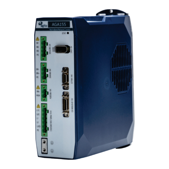
General Description Product Description 1.1 General Description The AGA155 series is a family of 220 VAC remote power amplifiers. AGA155 amplifiers are controlled by an AGM series Central-i master controller, which reads encoder values and current samples from amplifiers, performs control loops calculation, and generates PWM commands for each amplifier. -
Page 5: System Design
Input current @ 1-phase 120-240 VAC 4.5 A 15 A Input current @ 3-phase 208 VAC 10 A Peak current time 1.5 sec Output Frequency 0 – 599 Hz Short-circuit rating Rated short-circuit breaking capacity: 5 kA* AGA155 Product Manual Rev.1.3 Page 5... - Page 6 Commutation: Auto-phasing, by absolute offset Absolute EnDat 2.2 Hardware: Differential RS422/RS485, clock, data Clock frequency: 1 MHz Max. position bits: 32 bits Commutation: Auto-phasing, by absolute offset Hall sensors Opto-isolated 5V with internal or external power supply AGA155 Product Manual Rev.1.3 Page 6...
- Page 7 8 nanosecond Dimensions and Weight Feature Specification Unit dimensions (max) H=196.97 mm, W=65.80 mm, D=158.60 mm Package dimensions 244 mm x 92 mm x 198 mm Unit weight 1.29 kg Shipping weight 1.44 kg AGA155 Product Manual Rev.1.3 Page 7...
-
Page 8: Environmental Specifications
Environmental Specifications Figure 3. Product dimensions (mm) 1.5 Environmental Specifications Environmental Specifications Feature Specification Operating temperature* AGA155-CI-2A03: 0°C to 50°C AGA155-CI-2A06: 0°C to 50°C AGA155-CI-2A10: 0°C to 40°C Storage temperature -20°C to 70°C Operating humidity < 90% Storage humidity < 40%... -
Page 9: Safety
Attention All power connectors must be securely tightened before any operation. Warning Connectors X10, X9, and X7 are high power. Do not touch these connectors when the product is powered. AGA155 Product Manual Rev.1.3 Page 9... -
Page 10: Compliance
It is the responsibility of the machine or end-product manufacturer to ensure the final machine or end-product meets the requirement of any safety and EMC regulations. AGA155 Product Manual Rev.1.3 Page 10... -
Page 11: Installation
3.2.1 Mounting the AGA155 The heatsink on the back of the AGA155 includes a hole (at top) and a slot (at bottom) for mounting the unit. The AGA155 must be mounted vertically (book mounting), as shown in Figure 3. The AGA155 is mounted using 2 M4 screws. It is important to mount the product on metal panel for both grounding and secure connections. -
Page 12: Mounting Multiple Power Amplifiers
If amplifiers are mounted on a backplane, the backplane temperature must not exceed the limit defined section Safe Operating Area (SOA). It is recommended to install a cooling fan at the bottom of the cabinet for best circulation. Figure 4. Mounting multiple amplifiers within cabinet AGA155 Product Manual Rev.1.3 Page 12... -
Page 13: Electrical Installation
3.3.1 Power Wiring AGA155 is designed to operate directly from 110 VAC to 240 VAC mains power, which is supplied to bus voltage, to motor, and to logic power. Logic power input (L1C, L2C) uses 1-phase 120 VAC to 240 VAC input. -
Page 14: Circuit Breakers
Circuit breaker type Type C. 2-pole for L to N. 3-pole for 3-phase. Fuse type Time delay / slow blow Current rating AGA155 10A: 25 A AGA155 6A: 10 A AGA155 3A: 6 A Voltage rating AC 600 VAC Interrupt rating... -
Page 15: Ac Line Filter
A motor-enable request will create an error if PwrTemp is higher than 80°C. The following figure shows examples of safe operating cases for AGA155-CI-2A06. The SOA charts assume 90% duty cycle on PWM output continuously; that is, motors are moving at the maximum speed allowed by the bus voltage. -
Page 16: Grounding
3.3.6 Grounding It is recommended to install the AGA155 on a metal plate for better power dissipation, reduced EMI, and grounding connection. Make sure the plate is not painted. The heatsink of the AGA155 is electrically conductive and serves as the protective earth (PE) ground of the product. -
Page 17: Ground Domains
The enclosures and other external parts that may be touched by the user are in the safe domain. The AGA155 must be connected to protective earth (PE) and connected to the building’s ground. PE is protected with an earth-leakage circuit breaker (ELCB); hence it is safe to touch. Refer to Figure 7. -
Page 18: Electrical Interfaces
12–48 VDC – brake power input, up to 70W VBrake_Return Ground – brake power return Connector manufacturer Phoenix Contact Mating connector part number 1966114 (Wurth Electronics equivalent: 691364100004) (Degson equivalent: 15EDGKDM-3.5-04P-14) Connector pitch 3.5 mm Wiring AWG 18, insulation rated for 100V AGA155 Product Manual Rev.1.3 Page 18... -
Page 19: Interface X15: Safety
Safety_Feedback positive (collector) output Safety_Input_2+ Safety_Input_2 positive input Safety_Input_1+ Safety_Input_1 positive input Connector manufacturer Samtec Inc. Mating connector part number IPD1-04-D-K Crimp contact part number CC79L-2630-01-L (or equivalent) Wiring 26 AWG, insulation rated for 100V AGA155 Product Manual Rev.1.3 Page 19... - Page 20 The electrical characteristics of the Safety_Input_1 and Safety_Input_2 are identical to those of all other isolated digital inputs of the controller. The safety inputs implemented in the product are currently pending certification Functional Safety Standards. AGA155 Product Manual Rev.1.3 Page 20...
-
Page 21: Interface X7: Motor
Protective earth (motor power cable shield) Connector manufacturer Phoenix Contact 1942507 Mating connector part number (Wurth Electronics equivalent: 691340500004) (Degson equivalent: 2EDGKDM-5.08-4P-14) Connector pitch 5.08 mm Wiring 14-16 AWG, insulation rated for 600 V AGA155 Product Manual Rev.1.3 Page 21... -
Page 22: Interface X8: Static Brake
Mating connector part number 1942497 (Wurth Electronics equivalent: 691340500003) (Degson equivalent: 2EDGKDM-5.08-3P-14) Connector pitch 5.08 mm Wiring 18-20 AWG, insulation rated for 100 V Static Brake circuit diagram Figure 13. Electrical Interfaces – Static Brakes AGA155 Product Manual Rev.1.3 Page 22... -
Page 23: Interface X9: Regeneration
VB+, the Internal DC Bus power (pin 1). Connector manufacturer Phoenix Contact Mating connector part number 1942484 (Wurth Electronics equivalent: 691340500002) (Degson equivalent: 2EDGKDM-5.08-2P-14) Connector pitch 5.08 mm Wiring 14-16 AWG, insulation rated for 600 V AGA155 Product Manual Rev.1.3 Page 23... -
Page 24: Interface X10: Power
Plug or unplug the power connector only when power is off and after the bus LED has turned off (red LED visible at the side of the product). Plugging the power connector when power is on may cause power surges through connected devices and possibly damage them. AGA155 Product Manual Rev.1.3 Page 24... -
Page 25: Interface X13: Central-I
BI+_D45V_CI Bi-directional + BI-_D4CI_GND Bi-directional - Connector type RJ45 LAN 10/100Base-T connector Mating connector part number Any CAT5e compatible shielded connector Cable CAT5e or higher, standard Ethernet straight cable Wiring 26 AWG, 100 V AGA155 Product Manual Rev.1.3 Page 25... -
Page 26: Interface X2: Main Encoder
This port supports digital quadrature incremental encoders (AqB), analog sin/cos incremental encoders, absolute BiSS-C encoders, and absolute EnDat2.2 encoders. The type of encoder connected to the AGA155 is configured in the software. Figure 17. Main Encoder Connector Connector X2: ENC (MAIN) -
Page 27: Interface X4: Halls
Isolated digital input 1 (NPN or PNP, depending on connection of the common pin of this group). To use as Hall input, go to the Agito PCSuite Digital Input page, and configure as Hall A. Note: This input cannot be used for position lock (capture). - Page 28 Note – 5V supply limitation The 5V supply provided at pin 1 is limited to 0.5A per connector. The maximum total current provided by all the 5V pins in the product is limited to 1.5A. AGA155 Product Manual Rev.1.3 Page 28...
-
Page 29: Interface X5: System I/Os
Digital_Input_15 DInPort.bit(14) Isolated digital input 15 (NPN or PNP, depending on connection of the common pin of this group) Digital_Output_Common Common power pin for isolated digital outputs _Power (5 to 6) 5 to 6 AGA155 Product Manual Rev.1.3 Page 29... -
Page 30: I/Os Circuit Diagrams
PNP devices (external current sourcing devices). The input circuit of the opto-couplers includes two diodes. This enables use as NPN or PNP. AGA155 Product Manual Rev.1.3 Page 30... - Page 31 When using 5V Digital_Output_Common_Power in source mode, higher current (but less than the absolute maximum value of 250 mA) can be driven. However, the output high voltage will drop significantly. To maintain output high voltage at >4.5V, limit the current to 60 mA. AGA155 Product Manual Rev.1.3 Page 31...
- Page 32 For single-ended analog inputs, be sure to connect the return line to GND. Do not leave it unconnected. Input circuit bandwidth is 1 kHz, -40 dB/decade. The controller software provides the following parameters to control the analog input reading: Filter Offset Deadband Gain AGA155 Product Manual Rev.1.3 Page 32...
-
Page 33: Operation
Electrical Interfaces section. 2. Ensure that the safety port is connected before any operation. 3. Open Agito PCSuite software. Select CFG in CONFIG below and setup the parameters as follows: Figure 25. Operation Mode configuration 4. Click Next and set the motor type and number of pole pairs according to the test motor Figure 26. - Page 34 Figure 28. Position and Velocity Protection 7. Click Next to configure current and voltage limits. It is important to refer to motor’s specifications. The limits entered here must be within the motor operating limits to avoid damaging the motor. AGA155 Product Manual Rev.1.3 Page 34...
-
Page 35: Drive/Motor Overload Protection
Drive/Motor Overload Protection Figure 29. Current and Voltage Protection 4.2 Drive/Motor Overload Protection The following methods are used to protect the AGA155 from overload: Motor stuck Motor temperature protection using a PT100 or PT1000. 4.2.1 T Over Load protection In a transient condition, the motor can sustain a certain amount of energy that exceeds the continuous limit. - Page 36 Drive/Motor Overload Protection Figure 30. I In Agito PCSuite, the following parameters define the ���� ���� characteristics: Peak current Continuous current Peak time Figure 31. I T Settings Note – The I2T algorithm does not support thermal memory protection or thermal memory during power loss.
-
Page 37: Motor Stuck
4.2.3 Motor Temperature Protection If the motor temperature sensor option is selected, the AGA155 will monitor the PT100/1000 temperature sensor readings, and display warnings in the status window if the temperature is approaching the specified limit. -
Page 38: Tuning
If the system does not allow any motion during power-on or motor-on, use Hall sensors for commutation phasing. Connect Hall sensors to HALLS port and configure the first of the three inputs in the digital I/O page as Hall A. AGA155 Product Manual Rev.1.3 Page 38... -
Page 39: Current Loop Tuning
Click Calculate PI to calculate the current loop gains. Check both checkboxes for auto data recording and user predefined data recording. Click Apply Current Command to test the current loop performance. Figure 37. Current Loop Tuning AGA155 Product Manual Rev.1.3 Page 39... -
Page 40: Auto Velocity And Position Loop Tuning
Click Begin Identification to perform system identification. Figure 39. Begin System Identification When the identification is completed successfully, the plant’s transfer function will be displayed, as shown in the following figure. Figure 40. Typical Plant Transfer Function AGA155 Product Manual Rev.1.3 Page 40... - Page 41 PIV gains for this plant. Figure 42. Start Auto-Tuning calculation 4. Once Auto-Tuning is completed, click Write to Controller to download the calculated gains into the controller. Figure 43. Download the parameters to the controller AGA155 Product Manual Rev.1.3 Page 41...
- Page 42 5. Check the motion performance in the Motions Tab, set the required motion profile, and click Go 1 or Go 2 to move to Target 1 or Target 2. Record the motion data to analyze the motion performance in detail. Figure 44. Testing Motion AGA155 Product Manual Rev.1.3 Page 42...
-
Page 43: Manual Velocity And Position Loop Tuning
Figure 45. Manual Velocity Loop Tuning Figure 46. Typical Velocity Loop Performance Similarly, adjust proportional gain of position loop. In addition, adjust acceleration and velocity feedforward to improve performance. Click Apply Pos Command to check performance. AGA155 Product Manual Rev.1.3 Page 43... - Page 44 Figure 48. Typical Position Loop performance Repeat the configuration and tuning steps for all the axes connected to the product. Finally, test the motion according to the required motion profile, as in Figure 44. Testing Motion. AGA155 Product Manual Rev.1.3 Page 44...
-
Page 45: Maintenance And Servicing
(encoder) is faulty out of control or disconnected (free wheel) Position feedback sensor Go to Agito PCSuite’s CONFIG > FDBK page, toggle the Invert direction setting. is configured in wrong direction Encoder signal is Verify if the encoder signal is drifting even when the interfered by EMI noise in motor is physically locked or not moving. - Page 46 FLS or RLS of this motor. Check software software position and position limits and velocity limits at Agito PCSuite’s velocity limits. CONFIG > POS page. If the FLS or RLS signal is active when the digital input is changed, the FLS or RLS status will remain ON.
Need help?
Do you have a question about the AGA155 and is the answer not in the manual?
Questions and answers