Table of Contents
Advertisement
PO# TR179853
Manuf #: 753II-12-PC
0-12M OHM RESISTIVITY METER
Manuf #: CS10
RESISTIVITY SENSOR
Manuf #: CS14
2M OHM CALIB UNIT
REFERENCE #133418
RELAY
INTERNAL CO BATCH 203/2009
RE: ITEM ADDED
INTERNAL CO BATCH 330/2009
RE: ITEM AMENDED FROM EA TO CHG
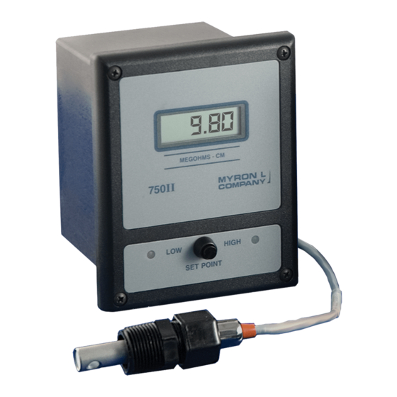
750 Series II
CONDUCTIVITY/TDS
RESISTIVITY
MONITOR/CONTROLLER
Operation
INSTALLATION • OPERATION • MAINTENANCE
Conductivity/TDS Models: 756II, 757II, 758II & 759II
Resistivity Models: 751II, 752II, 753II & 754II
ACCURACY • RELIABILITY • SIMPLICITY
&
Manual
16 November 17
NEW MODEL #753II-12-SC-PC
RES-DIGITAL MONITOR/CONTROL
AS PER QUOTE #106488 DATED
OCTOBER 28, 2009
INTERNAL CO BATCH 211/2009
RE: ITEM ADDED
INTERNAL CO BATCH 330/2009
RE: ITEM AMENDED FROM EA TO CHG
Water Quality Instrumentation
Accuracy • Reliability • Simplicity
Advertisement
Table of Contents


Need help?
Do you have a question about the 750 II Series and is the answer not in the manual?
Questions and answers