Advertisement
INSTRUCTION MANUAL
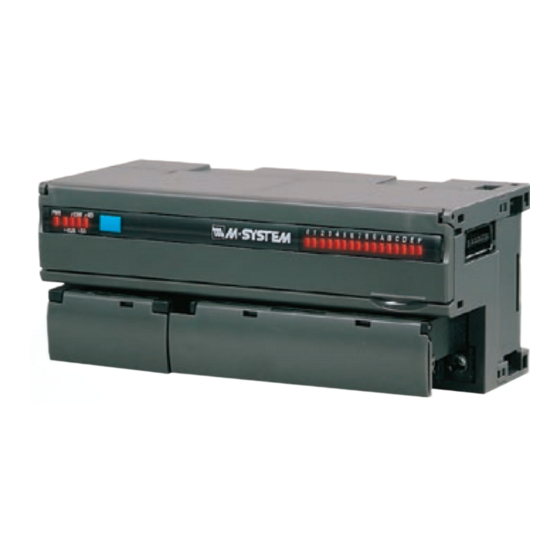
DC VOLTAGE OUTPUT MODULE, 2 points
(DeviceNet; external power supply)
BEFORE USE ....
Thank you for choosing M-System. Before use, please check
contents of the package you received as outlined below.
If you have any problems or questions with the product,
please contact M-System's Sales Office or representatives.
■ PACKAGE INCLUDES:
DC voltage output module ..................................................(1)
■ MODEL NO.
Confirm Model No. marking on the product to be exactly
what you ordered.
■ INSTRUCTION MANUAL
This manual describes necessary points of caution when
you use this product, including installation, connection and
basic maintenance procedures.
■ EDS FILE
EDS files are downloadable at M-System's web site: https://
www.m-system.co.jp
SEN TRONIC
POINTS OF CAUTION
■ CONFORMITY WITH EU DIRECTIVES
• The equipment must be mounted inside the instrument
panel of a metal enclosure.
• The actual installation environments such as panel con-
figurations, connected devices, connected wires, may af-
fect the protection level of this unit when it is integrated
in a panel system. The user may have to review the CE
requirements in regard to the whole system and employ
additional protective measures to ensure the CE conform-
ity.
■ GENERAL PRECAUTIONS
• Before you remove the unit or mount it, turn off the power
supply and output signal for safety.
• Before you remove the terminal block or mount it, make
sure to turn off the power supply and output signal for
safety.
• DO NOT set the switches on the module while the power
is supplied. The switches are used only for maintenance
without the power.
■ ENVIRONMENT
• Indoor use.
• When heavy dust or metal particles are present in the
air, install the unit inside proper housing with sufficient
ventilation.
• Do not install the unit where it is subjected to continuous
vibration. Do not subject the unit to physical impact.
• Environmental temperature must be within -10 to +55°C
(14 to 131°F) with relative humidity within 30 to 90% RH
in order to ensure adequate life span and operation.
■ WIRING
• Do not install cables close to noise sources (relay drive
cable, high frequency line, etc.).
• Do not bind these cables together with those in which
noises are present. Do not install them in the same duct.
• Be sure to close the terminal cover for safety.
■ AND ....
• The unit is designed to function as soon as power is sup-
plied, however, a warm up for 10 minutes is required for
satisfying complete performance described in the data
sheet.
056 222 38 18
mailbox@sentronic.com
AG
R7D-YV2A
MODEL
EM-7802-M Rev.5 P. 1 / 10
www.sentronic.com
Advertisement
Table of Contents

Related Manuals for M-system R7D-YV2A


Summary of Contents for M-system R7D-YV2A
- Page 1 (DeviceNet; external power supply) BEFORE USE ..POINTS OF CAUTION Thank you for choosing M-System. Before use, please check ■ CONFORMITY WITH EU DIRECTIVES contents of the package you received as outlined below. • The equipment must be mounted inside the instrument If you have any problems or questions with the product, panel of a metal enclosure.
-
Page 2: Component Identification
R7D-YV2A COMPONENT IDENTIFICATION ■ OPERATING MODE (*) Factory setting 1 2 3 4 5 6 7 8 • Extension: SW1-1, 1-2 SW1-1 SW1-2 EXTENSION CNFG. NODE ADD. B.RATE No extension (*) Discrete input, 8 or 16 points Discrete output, 8 or 16 points 2 3 4 •... - Page 3 R7D-YV2A PC CONFIGURATOR The following parameter items can be set with using PC Configurator Software (model: R7CON). Refer to the users manual for the R7CON for detailed operation of the software program. ■ INTERFACE SETTING PARAMETER SETTING RANGE DEFAULT SETTING Communication Timeout 0.0 –...
-
Page 4: Terminal Connections
R7D-YV2A TERMINAL CONNECTIONS Connect the unit as in the diagram below. ■ EXTERNAL DIMENSIONS unit: mm (inch) 115 (4.53) 17 (.66) 54 (2.13) DIN RAIL 35mm wide 2 3 4 30 (1.18) [5 (.20)] TERMINAL BLOCK for DeviceNet, POWER 6 (.24) 10–M3 SCREW... -
Page 5: Data Allocation
R7D-YV2A DATA ALLOCATION ‘Begin’ address is determined by the R7D’s node address and the master setting. • Example 1. Analog Output Module + R7D-EA16, without Status Output Data Input Data Begin +0 R7D-EA16 Begin +0 Analog Output Module • Example 2. Analog Output Module + R7D-EC16x, with Status... -
Page 6: Wiring Instructions
R7D-YV2A ■ STATUS Bit 0 to 7: Analog output module shows ‘0’ at the same address. Bit 8 to 10: Shows the power supply status. Remains “0” Remains “0” Remains “0” Remains “0” Remains “0” Remains “0” Remains “0” Remains “0”... - Page 7 CE mark which shows that the product conforms with the requirements of EU Directive. Each EU Directive describes the scope of apparatuses to which that EU Directive is applied. M-System’s R7D must conform with EMC Directive. Each Directive states only basic requirements. In order to mark the CE on an assembled machinery equipment, its manufac- turer needs to check the overall conformity with Directives applicable to it.
- Page 8 R7D-YV2A • Points of cautions applicable when installing the R7D Series Install the R7D Series inside Keep the opening for a control panel. ventilation as small as posible. Attachment part of earth clamp should be fixed with screw in conduction with the Attach an electro- internal panel plate.
- Page 9 R7D-YV2A ■ WARNINGS AND CAUTIONS WHEN LAYING CABLES Signal cables connected to the R7D contain high-frequency components. Since these cables has the same effect as an anten- na, they emit these high-frequency components to the external space as noise or overlaps noise from the external space on themselves.
- Page 10 R7D-YV2A • Points of cautions applicable when wiring the R7D Series Keep the wires away from each other at both ends of the filter. Noise Filter Shielded Cable Earth To external apparatus Clamp Keep the cable as Remove a part of the shielded short as possible.
Need help?
Do you have a question about the R7D-YV2A and is the answer not in the manual?
Questions and answers