Advertisement
Advertisement

Subscribe to Our Youtube Channel
Related Manuals for Midea CCM15


Summary of Contents for Midea CCM15
- Page 1 FULL DC INVERTER SYSTEMS OWNER´S & INSTALLATION MANUAL DATA CONVERTER GATEWAY CCM15 C O M M E R C I A L A I R C O N D I T I O N E R S S D V 4 Thank you very much for purchasing our product.
- Page 2 This manual gives detailed description of the precautions that should be brought to your attention during operation. In order to ensure correct service of the wired controller please read this manual carefully before using the unit. For convenience of future reference, keep this manual after reading it.
-
Page 3: Table Of Contents
Table of Contents I. Safety Precautions..................1 II. Installation and Operation of the Data Converter..........3 III. APP Function Description................12 IV. Web Client Operation................37 V. Remote Web Client Operation..............38... -
Page 4: Safety Precautions
I. Safety precautions The following contents are stated on the product and the operation manual, including usage, precautions against personal harm and property loss, and the methods of using the product correctly and safely. After fully understanding the following contents (identifiers and icons), read the text body and observe the following rules. - Page 5 Icon description lcon Meaning It indicates forbidding. The forbidden subject-matter is indicated in the icon or by images or characters aside. It indicates compulsory implementation. The compulsory subject-matter is indicated in the icon or by images or characters aside. Warning Please entrust the distributor or professionals to install the unit.
-
Page 6: Installation And Operation Of The Data Converter
II. Installation and Operation of the Data Converter 1. System structure diagram The system mainly includes the central air conditioning system, data converter, router, App, cloud server, and Web client. The user can monitor the air conditioning system via App or Web client. - Page 7 LAN cable to connect multiple CCM15 gateways, associate CCM15 gateways with one router. For the configuration, see section 3.1. Note: The new CCM15 is compatible with the V5X, V4+S, V4+R and Mini VRF outdoor units For more information, please contact the technical support engineer...
- Page 8 2. Hardware instruction Fig.3.1 Structure dimension drawing...
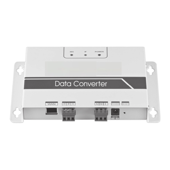
- Page 9 Status indicator light Input Voltage:DC5V Connect to the Ethernet communication RESET terminal 485 terminal Power supply terminal Fig.3.2...
- Page 10 3. Instructions 1. Unpack the packing box to see if the accessories are all in readiness. Data converter is shown as the following figure: Name Qty. Outline Data Converter Installation operation manual Power adaptor Wiring 3-terminal and 1 bags of fixed screws...
- Page 11 2.Take the data converter out and power it on to see if the device is normal ( POWER indicator lights up) POWER indicator lights up Fig.3.3 3. Data converter installation precautions a. Don’t install it in the place where flammable gas leaks easily. Once flammable gas leakage occurs and stagnate around the device, it may result in fire.
- Page 12 Operating Colour Description indicator status When the indicator flashes, it indicates Green Flash that an air conditioner is connected. When it flashes, it indicates that the data Green Flash converter is accessing the Ethernet. POWER Steady on Power supply of the system is normal. POWER Air conditioner Ethernet...
- Page 13 VRF system via WAN. The App client on the data converter, log in to the embedded smart phones and Web client are available. Function list of App client ① CCM15 list. ① ② CCM15 management. ③ Account management. ④ Group management.
- Page 14 Web function list "AC Control": air conditioner control "Booking Control": scheduled operations "Operation logs": operation logs "User group": group management APP download IOS: Go to APP Store seach “Green Control Intensity” to download the app Android: Please ask to your Intensity Contractor for reference of the Android App.
-
Page 15: App Function Description
III. APP Function Description 1. Registration Function 1-1 Registration Code Before registering an account, the user must enter the registration code, as shown in the following figure. Open App client on the smart phone. Enter the registration code, such as Intensity, which is the first step. - Page 16 1-2 Account Registration A registered account is used to manage devices and set management permissions. The registered account can also be used to log in to the App and Web clients. Procedure: Click "Register". Enter a valid email After registration is account and password.
- Page 17 2 Virtual function The virtual experience function is used for showing the main interface , AC control, booking control and so on. Operation only available for choosing the unit of the temperature and setting the AC, the other menu and function are invalid in this function.
- Page 18 2. App Configuration Refer to the guide to connecting the CCM15 and port XYE of the outdoor unit. Connect the CCM15 to the router. After login via App, the main interface prompts the user to configure the CCM15, as shown in the following figure: ①...
- Page 19 C. The wireless router must access the Internet. ①Select a configuration manner. ②The App will search for the CCM15 devices on its LAN and displays the IP address of each CCM15 gateway. As shown in the figure above, ② displays multiple CCM15 devices found.
- Page 20 ③ Select a configuration manner. The subsequent steps are the same as those for configuring the CCM15 via a network cable. Repeat the preceding steps to add multiple CCM15 devices until all the CCM15 devices are...
- Page 21 2) Click "Scan QR code". It goes to the QR code scanning interface. Scan the QR code shared with other users to complete configuration. Note: When the CCM15 is configured for the first time, the user must configure it via a network cable.
- Page 22 3 Editing an Area 3-1 Adding and Deleting an Area Adding an area: Click "+", as circled in the figure above. On the displayed interface, click "Add Area". Enter the name of the new area in the text box. Click "Save".
- Page 23 Deleting an area: On the selected area, slip left. Click "Delete" to delete the area. Click "Edit" to edit the area name.
- Page 24 3-2 Adding a Device to an Area After an area is added, it goes back to the area display interface. Click the area to which a device is added. Click "Add Device". Select the device to be added. Click "OK".
- Page 25 3-3 Editing a Device in an Area Click the icon indicated by ① at the upper right corner, as shown in the figure above. Click "Device management". The device management interface is displayed. Click "Add Device" indicated by ② to add a device or "Remove Device" to delete a device.
- Page 26 Device state Screening statistics device states Distinguishing device states by using Area list different colours Statistics of device states: This area displays the number of air conditioners in each state. Distinguishing device states by using different colours: This area displays the air conditioners in different states by using different colours, as shown in the following figures:...
- Page 27 HEAT COOL Screening device states: This area displays the air conditioners in the selected state. 3-4 Area Control Main Interface Area control-Mode Area control-Items Area list to be locked Area list: It displays area name, the number of running air conditioners in the area, and the total number of the air conditioners in the area.
- Page 28 Area control: On the area control interface, ambient temperature is not displayed. The user can set temperature between 17°C and 30°C (62°F and 86°F) and select a fan speed (low, medium, high, and auto). Locking: The user can lock mode, cooling temperature, heating temperature, fan speed, and remote control.
- Page 29 ⑤ Locking: The user can lock mode, cooling temperature, heating temperature, fan speed, and remote control. ⑥ Power on or off. ⑦ Set temperature between 17°C and 30°C (62°F and 86°F). Note: If an air conditioner fails, the main interface displays the fault and the user cannot operate the interface.
- Page 30 ③ It is an interface for renaming a device. Note: The new CCM15 is compatible with the V5X, V4+S, V4+R and Mini VRF outdoor units and all kinds of indoor units except for the HRV and the Fresh Air Processing Unit.
- Page 31 5. Scheduled Control Function ① Displayed in a list Displayed in a chart Click the icon indicated by ①. The scheduled operation interface is displayed. Scheduled operations can be displayed in a chart or in a list.
- Page 32 After parameters are set, click at the upper right corner to save the settings. 6 User Group Management 6-1 Inviting and Removing a User Select a CCM15 device from the list, and then click "Group Management". The following interface is displayed:...
- Page 33 ② ① ① "Invite User": If a QR code is displayed, a user can scan it to join the user group. The QR code is valid within 30 minutes. Up to 10 users can join one user group. ② "Remove User": Click it to remove a user from a user group.
- Page 34 6-2 Permission Management The figure above shows all the permissions of the members in a user group: "Invite/Re- move users", "Change device information", "Device control", "Area control", "Lock function", and "View operations log".
- Page 35 7 Operation Logs Click "Operation logs" on the left. The "Operation logs" interface is displayed, as shown in the following figure: ① ② ③ ① "Device Operation Record" ② "Device Log" ③ "Login Record"...
- Page 36 7-1 Device Logs ① ② Device logs include status logs and malfunction logs: ①"Status Log": It displays gateway name, time, and status. ②"Malfunction Log": It displays device number, malfunction occurrence time, and error code.
- Page 37 7-2 Device Operation Records The "Device Operation Record" displays operation records of each device, including mode, operation time, user name, and execution status.
- Page 38 7-3 Login Records Login records are classified into App login records and Web login records: ① "APP": It displays login user name and login time via the App client. ② "Web": It displays login user name and login time via the Web client.
- Page 39 8 Account Management Click "Account Management". The account management interface is displayed, as shown in the following figure: ① Click the user name. The "Rename" dialog box is displayed. Enter a new name, and then click "Save". ② Click "Change Password". On the "Change Password" interface, enter the old and new passwords.
-
Page 40: Web Client Operation
The embedded Web page of the CCM15 gateway is displayed: Click "Config." to edit the IP address of the CCM15 gateway. The IP address can be set to a dynamic IP address or a static IP address. -
Page 41: Remote Web Client Operation
V. Remote Web Client Operation 1. Log in Browser support: IE 10 or above, Firefox Chrome Safari Operating systems: Windows7 or above Mac OS The login interface is displayed. Enter the registered email address in the "User name" text box and password in the "Password" text box. Click "Login". An account can only be registered on the App client. - Page 43 ① It is a function list. It lists "Device Control", "Booking Control", "Operation logs", and "User group". ② It is a CCM15 list. It displays a list of CCM15 gateways configured via the App client. Up to 10 gateways are supported.
- Page 44 3. Area Management 3-1 Area Control Function ⑥ ⑩ ⑤ ① ② ③ ④ ⑦ ⑧ ⑨ Click the area name , the right area will display the control interface "Mode": sets mode. "Speed": sets fan speed. "Swing": determines whether to enable swing mode.
- Page 45 3-2 Single Control Function of Air Conditioners ① ② The function list is the same as that of area control. Refer to the area control function. In single control mode, the user can select the air conditioner model, indicated by ①. The area on the left displays air conditioners, indicated by ②.
- Page 46 3-4 AC statistics and filter function AC states statistics Display: calculate the number of AC with different states in one CCM15. The available states include: cooling, heating, fan only, off, lock and error. The auto mode is included in the cooling mode.
- Page 47 4-1 Main Interface The main interface displays scheduled operation type, device, scheduled time, mode, temperature, fan speed, week, and repeated or not. Click "Delete" to delete a scheduled operation. Click "Edit" to edit a scheduled operation. Click "Add" to add a scheduled operation.
- Page 48 1. "Timer start": On this tab page, set scheduled time, device, mode, temperature, fan speed, and week, and determine whether to repeat this scheduled operation. 2. "Timer shutdown": On this tab page, set scheduled time, device, week, and determine whether to repeat this scheduled operation. 5.
- Page 49 5-1 Operation Records The items displayed on the "Operation Record" tab page are the same as those displayed on the App client, including mode, time, user name, and execution results. 5-2 Status Logs The "Status Log" tab page displays online statuses of air conditioners.
- Page 50 5-3 Malfunction Logs The "Malfunction Log" tab page displays malfunction information and error codes. 5-4 Login Records Both "App Login Record" and "Web Login Record" tab pages list login information.
- Page 51 6 User Group Management ② ⑦ ③ ⑤ ⑥ ④ ① ① Click it to display user group management. ② Click it to rename a group. ③ Click it to share a QR code. ④ It lists users. ⑤ Click it to set permissions. ⑥ It is a device management area.
- Page 52 6-2 Renaming a User Group Click "Rename" to rename the selected user group. 6-3 Inviting a User Click "QrCode" to generate a QR code of the user group. Up to 10 users are supported.
- Page 53 6-4 Deleting a User Group Click "Ungroup" to delete the selected user group. 7 setting Click to enter into the setting interface ④ ① ② ③ modify unit of temperature: Celsius, Fahrenheit set supported languages: English, French and Spanish modify of the login password...
Need help?
Do you have a question about the CCM15 and is the answer not in the manual?
Questions and answers
Hello, I have the M-Control app for my AC units, but I need the IOS app also. Could you please let me know which app I can use for this?
The iOS app that can be used for the Midea CCM15 air conditioner with M-Control functionality is the "App client" mentioned in the manual. The manual states that the app is available for both iOS and Android versions.
This answer is automatically generated