
Subscribe to Our Youtube Channel
Related Manuals for Midea M-INTERFACE


Summary of Contents for Midea M-INTERFACE
- Page 1 INSTALLATION & OWNER’S MANUAL M-INTERFACE GATEWAY Thank you very much for purchasing our product, Before using it, please read this manual carefully and keep it for future reference.
-
Page 2: Table Of Contents
CONTENTS PAGE SAFETY INFORMATION ..........................1 ACCESSORIES ............................2 M-INTERFACE GATEWAY CONTROLLER INSTALLATION ..............3 SYSTEM INTRODUCTION .......................... 8 SETTINGS ..............................15 OPERATION INSTRUCTIONS ........................18 TROUBLE SHOOTING ..........................28 1. SAFETY INFORMATION The following contents are stated on the product and the operation manual, including usage, precautions against personal harm and property loss, and the methods of using the product correctly and safely.After fully understanding the following contents (identifiers and icons), read... -
Page 3: Accessories
Do not spray flammable aerosol to the M-INTERFACE gateway Forbid controller directly. Otherwise, fire may occur. Usage Do not operate with wet hands or let water enter the M-INTERFACE Warning Forbid gateway controller. Otherwise, electric shock may occur. 2. ACCESSORIES... -
Page 4: M-Interface Gateway Controller Installation
Installation should comply with the local rules; ■ Ensure there has enough installation space, for heat dissipation of the community service ■ network device nearby. 3.1 M-INTERFACE Gateway controller structure 1) Front view of M-INTERFACE gateway controller (Unit: mm) Fig.3-1 Installation & Owner's Manual... - Page 5 2) Side view of M-INTERFACE gateway controller (Unit: mm) 319±1 Fig.3-2 3) Detailed drawing of installation holes (Unit: mm) Installation precautions: ■ Must be installed indoors, guarantee the gateway controller installation must be higher than the ground 50 cm; ■...
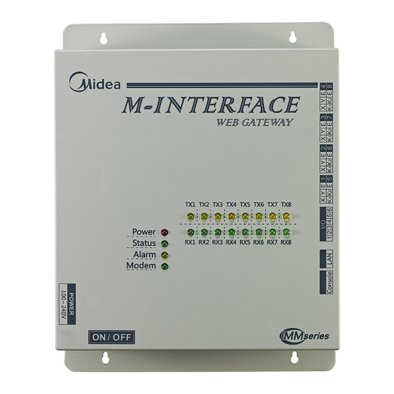
- Page 6 Fig.3-5 Power ON/OFF switch M-INTERFACE gateway has 8 M-net terminals, 1 LAN terminal, 8 M-net terminal indication lamps, 4 status display lamps (Power, Status, Alarm, and Modem) and power switch. Connect to the central air- conditioning system through the M-net terminal, and connect the local area network or Internet network through LAN terminal.
- Page 7 2) Terminal figure LAN terminal I/O terminal 1 2 3 4 5 6 Console terminal Fig.3-6 3) LED indication lamp instructions Table.3-1 Indication lamp Color Indication lamp instructions TX1~TX8 Yellow No.1-8 sending terminals indication lamp RX1~RX8 Green No.1-8 receiving terminals indication lamp Power Power indication lamp Status...
- Page 8 4) Specification parameters of M-INTERFACE gateway controller Table.3-2 Voltage range Single phase AC 100~240V, 50/60 Hz Power specification Consumed power Max.15W Voltage fluctuation Rated value ±10% Ambient temp. 0~50℃ Using conditions Ambient humidity 25%~90% Storage temp. -20~60℃ Capacity Insulated resistance When it is DC 500VM, it will over 50MΩ...
-
Page 9: System Introduction
4. SYSTEM INTRODUCTION M-INTERFACE is a Central Air-conditioning multi-connected devices’ gateway which based on WEB, is an important part of Intelligent Manager system (IMM). Connect to Central Air-conditioning devices through the M-net terminal. It can connect the multi-connected devices through its M-net connector (M-net connector is XYE communication terminals and K1K2E communication terminals);... -
Page 10: Local Network Connection
Safari (5.1 or above). 4.4 Local network connection M-INTERFACE gateway can connect to the LAN network through switch. IP address of computer or similar devices must in the same subnet area as the IP address of M-INTERFACE gateway. - Page 11 255.255.255.0. If the computer only insert the M-INTERFACE network, then use the way of configuring single IP; if the computer also inserts the local network beside M-INTERFACE network, then use the way of configuring several IP. Methods as follow (Take windows 7 system for example).
- Page 12 Fig.4-3 Type “ipconfig” in the above figure, then the interface will display the local dynamic IP address, and it will write this IP address into the property dialogue box, and finish the statistic IP address configuration, details please consult the local network administrator. After the statistic IP address configuration, open the property dialogue box again, select the “Advanced”, and display the TCP/IP setting dialogue box as follow: Fig.4-4...
- Page 13 4.4.2 Local LAN access If there is a computer or other similar device of same subnet area as M-INTERFACE in LAN, then type the link address of M-INTERFACE gateway (e.g.: http://192.168.100.40) on the browser address bar can visit the M-INTERFACE WEB interface to operate the air-conditioning device. The local visit topology structure as follow display: Fig.4-5...
- Page 14 If the company has a public network address, then it needs to send a mapping of a terminal in fire wall to M-INTERFACE gateway; when the computer or similar device of outside network visit the M-INTERFACE, then take http:// public network IP: visit as a terminal. E.g.: http:// 203.208.60.72:6080.
- Page 15 Display the entire situation of refrigerant system; include quantities of indoor and outdoor units in refrigerant system, ammeter quantity and communication quality between single device and M-INTERFACE gateway. 3) Setting Offer the centralize controller configuration, time setting, IP setting and User management etc.
-
Page 16: Settings
Do the following settings before using the M-INTERFACE gateway. Only the administrator can make the following operation. 5.1 M-INTERFACE setting M-INTERFACE gateway setting as the following display, the setting of baud rate and the energy- requiring compatibility please refer to IMM TECHNOLOGY MANUAL. Fig.5-1 5.2 Time setting... -
Page 17: Ftp Setting
5.3 IP setting If add the M-INTERFACE into local network, then it needs to reset the M-INTERFACE IP address, and click “OK ” button after setting. If many M-INTERFACEs in the same network area, then the IP address could not be repeated. - Page 18 5.5 Multi-pipe setting Setting contents include: system mode(2:Two-pipe system, 3:Three-pipe system), auto cooling and heating(only valid for Three-pipe system), temperature different value(ΔT: different value of setting temperature and room temperature), changing time interval. Fig.5-5 Installation & Owner's Manual...
-
Page 19: Operation Instructions
6. OPERATION INSTRUCTIONS 6.1 User login Type the link address of M-INTERFACE gateway on the browser address (take windows 7 system, IE for example), then can visit the M-INTERFACE WEB login interface. Fig.6-1 Enter the login page, user operates as follow to enter into system: 1) Select user name, type in password;... - Page 20 6.2 Main interface introduction WEB home page display as follow: Main menu Information display Submenu Fig.6-2 Home page: main menu, submenu and information display. Main menu: display all functions of system, include “Device monitoring”, “System mapping”, “Setting”, “Device information” and “Help” etc.
- Page 21 The operating statuses of indoor unit are cool, heat, fan, OFF, power off, error and lock. Different operating statuses will has different pictures. Click a single indoor unit, then it will display the operat- ing status information of this indoor unit on the bottom of page, include ON/OFF status, operating mode, device name and HP etc.
-
Page 22: System Monitoring
4) Control the operating status of outdoor unit Priority selecting content of mode include: 5 modes of heating priority, cooling priority, multi-opening priority, heating only and cooling only, this setting is only valid for water source multi-connected model. Fig.6-6 6.3.2 System monitoring Display all the indoor units of refrigerant system as the system way, has the function of checking and controlling the operating status of indoor unit. - Page 23 1) Check the detailed information of indoor unit Fig.6-7 Select the refrigerant system, the page will display all the indoor unit of the refrigerant system, and then click the indoor unit and it will display its operating status include ON/OFF state, operating mode, fan state, indoor unit quantity, error protection, ammeter readings etc.
- Page 24 Click the “ ” button in the page, then can control the indoor unit operating status page. Select one or more air-conditioners, set the controlling parameters, include “ON/OFF setting”, “Mode setting”, “Swing setting”, “Temp setting” and “Fan speed setting”, and then click the “Send” button to send the control order, and the page will display success or fail information.
- Page 25 Communication quality between single Communication quality device and M-INTERFACE gateway 6.5 Setting For safety operation of M-INTERFACE, it only offer the “User management” function (Other functions refer to the IMM TECHNOLOGY MANUAL). 6.5.1 User management Offer the password changing function.
- Page 26 Fig.6-10 Click “OK” button after changing. 6.5.2 Refrigerant system mapping Output the topology document, the auto topology structure as follow display: Fig.6-11 Installation & Owner's Manual...
-
Page 27: Device Information
6.5.3 Gateway controller status Display the status information of gateway controller. Fig.6-12 6.6 Device information Check the indoor/outdoor device information in the refrigerant system. 6.6.1 Indoor unit information Select the refrigerant system, click the “Indoor Info”, and the will show up the indoor unit information display page, as follow: Fig.6-13 Installation &... - Page 28 The display contents include: serial port (terminal no. which inserted into), address, physics location, sales model, fan power, E-heater power and maintenance status information. 6.6.2 Outdoor unit information Select the refrigerant system, click the “Outdoor Info”, and the will show up the outdoor unit informa- tion display page, as follow: Fig.6-14 The display contents include: serial port, address, physics location and sales model.
-
Page 29: Troubleshooting
7.1 Unable to enter into the login page Type the IP address of M-INTERFACE gateway in the browser, if it cannot display the login page, which may be error of network; if it’s needed, ask the IT administer to check the local network. Check the computer whether stay the same network area with the N-INTERFACE gateway. - Page 30 When operating the page and no respond or display “No connection” message, that means the network communication between computer and M-INTERFACE gateway was broke off, and it needs to check the computer network card, IP setting, and the switch board, as well as the IP of the M-INTER- FACE gateway and LAN terminal network card indication lamp of M-INTERFACE gateway.
- Page 31 MD12IU-013EW 16110800000047...
Need help?
Do you have a question about the M-INTERFACE and is the answer not in the manual?
Questions and answers