
Related Manuals for REDSTONE RGW Series

Summary of Contents for REDSTONE RGW Series
- Page 1 RGW Series VoIP Gateway User Manual Redstone Systems, Inc. Redstone Manual RGW Series User Manual RGW4 RGW8 RGW48 RGW96 Website: http://www.redstonesystems.com Email: gs@redstonesystems.com Document Version: 202205...
-
Page 2: Amendment Records
Amendment Records Document Rev. 01 (May 2022) This manual is applicable to Redstone’s RGW series VoIP Gateway V371. Copyright © 2022 Redstone Systems, Inc. All Rights Reserved. All or part of this document may not be excerpted, reproduced and transmitted in any form or by any means... -
Page 3: Table Of Contents
RGW Series VoIP Gateway User Manual Contents Amendment Records ..............................2 Contents ................................... 3 Figures ....................................6 Tables ....................................9 1 Overview ..................................11 1.1 Product Introduction ................................11 1.2 Functions and Features ..............................12 1.3 Equipment Structure ................................13 1.3.1 RGW4.................................. - Page 4 User Manual RGW Series VoIP Gateway 2.4.2 Trunk Features ................................ 50 2.4.3 Trunk Batch (Unavailable on the RGW4) ......................52 2.4.4 Trunk Characteristics ............................. 53 2.5 Routing ....................................55 2.5.1 Digit Map .................................. 55 2.5.2 Routing Table ................................57 2.5.3 Examples of Routing Rules ........................... 62 2.6 Advanced Configuration ..............................
- Page 5 RGW Series VoIP Gateway User Manual 3 Appendix: VLAN Configuration ..........................100 3.1 Automatic Discovery (Not supported by RGW4/RGW8) ..................... 100 3.1.1 LLDP ..................................101 3.1.2 DHCP ..................................104 3.2 Manual Configuration ............................... 105 3.2.1 Single VLAN ................................105 3.2.2 Multi-Service VLAN ............................... 106 4 Making an OpenVPN Client Certification (RGW4/RGW8) ................
-
Page 6: Figures
User Manual RGW Series VoIP Gateway Figures Figure 1-1 RGW4 Front Panel ..............................13 Figure 1-2 RGW4 Back Panel ..............................14 Figure 1-3 RGW8 Front Panel ..............................15 Figure 1-4 RGW8 Back Panel ..............................16 Figure 1-5 RJ45 to RS232 Serial Cable ..........................16 Figure 1-6 USB to RS232 Converter Cable .......................... - Page 7 RGW Series VoIP Gateway User Manual Figure 2-32 SIP Related Configuration Interface ........................69 Figure 2-33 RADIUS Configuration Interface .......................... 72 Figure 2-34 Greeting Interface ..............................73 Figure 2-35 Call Progress Tone Configuration Interface ....................... 74 Figure 2-36 Feature Codes Configuration Interface ....................... 76 Figure 2-37 Clock Service Interface ............................
- Page 8 User Manual RGW Series VoIP Gateway Figure 3-14 SIP Data Packet Carrying VLAN Tag of the Voice VLAN in the Multi-Service VLAN Mode ..... 111 Figure 3-15 RTP Data Packet Carrying VLAN Tag of the Voice VLAN in the Multi-Service VLAN Mode ....111 Figure 3-16 RTP Data Packet Carrying VLAN Tag of the Management VLAN in the Multi-Service VLAN Mode ..
-
Page 9: Tables
RGW Series VoIP Gateway User Manual Tables Table 1-1RGW Series Gateway Hardware Specifications....................11 Table 1-2 Configuration Combination of RGW4 ........................13 Table 1-3 Description of RGW4 Front Panel ......................... 14 Table 1-4 Description of RGW4 Back Panel .......................... 14 Table 1-5 Indicator Status of RGW4 ............................ - Page 10 User Manual RGW Series VoIP Gateway Table 2-22 Routing Destination ............................... 61 Table 2-23 NAT Configuration Parameters..........................64 Table 2-24 Auto Provisioning Configuration Parameters ..................... 65 Table 2-25 SNMP Configuration Parameters ........................66 Table 2-26 TR069 Configuration Parameters ........................66 Table 2-27 Media Stream Configuration Parameter ......................
-
Page 11: Overview
User Manual Overview 1.1 Product Introduction RGW Series intelligent VoIP Gateways (RGW Gateways) are designed to bridge the traditional telecom terminal device into IP networks through SIP or MGCP protocols. The main applications include: For carriers and value-added service providers to provide telephone, fax and voice-band data services ... -
Page 12: Functions And Features
User Manual RGW Series VoIP Gateway Hardware for RGW series gateways uses high-performance CPUs, ensuring that each product of the series can achieve full-capacity concurrent calls with high speech quality. RGW gateways software adopts the stable and reliable embedded Linux operating system (OS),... -
Page 13: Equipment Structure
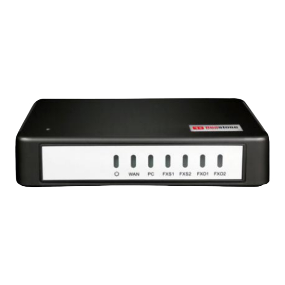
Support the VPN client (only available with the RGW4/RGW8) Support VLAN Support Redstone Cloud, allowing Redstone devices located behind NAT or firewall to be easily accessed. 1.3 Equipment Structure 1.3.1 RGW4 The RGW4 adopts a compact plastic structural design and can be placed on a desk. -
Page 14: Figure 1-2 Rgw4 Back Panel
User Manual RGW Series VoIP Gateway Table 1-3 Description of RGW4 Front Panel Item Description Power Indicator WAN interface indicator PC interface indicator FXO/FXS FXS/FXO port indicator RGW4 Back Panel Figure 1-2 Table 1-4 Description of RGW4 Back Panel Item... -
Page 15: Rgw8
RGW Series VoIP Gateway User Manual Indicator Status Description Steady green A WAN connection is established without any service flow. Blinking green A WAN connection is established with service flow. (green) WAN interface is disconnected. Steady green A link is connected without any service flow. -
Page 16: Figure 1-4 Rgw8 Back Panel
User Manual RGW Series VoIP Gateway Item Description WAN interface indicator PC interface indicator VOICE FXS/FXO port indicator RGW8 Back Panel Figure 1-4 Table 1-9 Description of RGW8 BackPanel Item Description The console port is used for local management and testing. PCs can be connected to device by linking the RS232 port to CON port. -
Page 17: Rgw48
RGW Series VoIP Gateway User Manual Indicator Status Description The WAN interface failed to acquire the IP address. Possibly the WAN interface is not connected to a network cable, the WAN interface Steady red address fails to be acquired by DHCP, the IP addresses are conflicted, and the PPPoE dialing fails. -
Page 18: Figure 1-7 Rgw48 Front Panel
User Manual RGW Series VoIP Gateway uses a RJ-45 socket and is connected to the distribution panel in the equipment room by using CAT-5 cables. RGW48 offers up to 48 analog line ports and supports the following configurations: Table 1-11 Configuration Combination of RGW48... -
Page 19: 4Rgw96
RGW Series VoIP Gateway User Manual RGW48 Back Panel-AC Figure 1-8 Table 1-13 Description of RGW48 Back Panel Item Description Ground pole Indicator, see Table 1-14 for description PWR/STU/ALM USB interface Configuration interface (CON), used for local management and debugging ETH1/ETH2 Two 10/100 MbpsEthernet ports (RJ45). -
Page 20: Figure 1-9 Rgw96 Front Panel
User Manual RGW Series VoIP Gateway The interface card of RGW96uses a RJ-45 socket and is connected to the distribution panel in equipment room using CAT-5 cables supplied with the unit. The device of RGW96can hold four interface cards to flexibly configure FXS and FXO ports, and each card equips 24 ports. -
Page 21: Figure 1-10Rgw96 Back Panel-Ac
RGW Series VoIP Gateway User Manual RGW96 Back Panel-AC Figure 1-10 RGW96 Back Panel-DC Figure 1-11 Table 1-19 RGW96 Back Panel Item Description To restore the device to factory default, press the RST for more than 3 seconds and release it when the STU light starts blinking in red. -
Page 22: Table 1-21Rgw96 System Operation State
User Manual RGW Series VoIP Gateway Indicator Status Description Blinking green The device is running. Steady red The device is starting. (red, green) Blinking red The device is under diagnosis. The device is locked. No alarm The alarms indicated by the blinking alphabetic messages C/E/T on LED Blinking red dot-matrix are generated. -
Page 23: Web Management Page
RGW Series VoIP Gateway User Manual 1.4 Web Management Page 1.4.1 Layout The Web GUI of the RGW series gateways includes a general information display bar, a general operation bar, a menu bar, and a configuration area. Web GUI Figure 1-12... -
Page 24: Parameters Setting
RGW Series VoIP Gateway User Manual Parameters Setting 2.1 Login 2.1.1 Obtaining Gateway IP Address RGW4/RGW8 Gateways start DHCP service by default, and automatically obtain an IP address on the LAN; you can use the factory-default gateway IP address if it is unable to be obtained (e.g. when connected directly with a computer).1... -
Page 25: Privileges Of Administrator And Operator (Web Gui)
RGW Series VoIP Gateway User Manual prompt like "There is a problem with this website's security certificate" may occur. Click Continue to this website to access the login page. Figure 2-1 Login Interface for RGW8 Gateway Configuration 2.1.3 Privileges of Administrator and Operator (Web GUI) Login users are classified into administrator and operator. -
Page 26: Accessing Through Ssh
User Manual RGW Series VoIP Gateway The gateways allow multiple users to log in if needed. When multiple administrators log in, the first can modify, while others (displayed as Viewer) may only browse. The system will confirm timeout if users do not conduct any operation within 10 minutes after login. -
Page 27: Network
RGW Series VoIP Gateway User Manual Figure 2-2 Status Interface 2.2.2 Network After login, click Basic>Network to open the configuration interface. Figure 2-3 Network Configuration Interface (/RGW4/RGW8) Redstone Systems, Inc. -
Page 28: Figure 2-4 Network Configuration Interface (Rgw48/Rgw96)
User Manual RGW Series VoIP Gateway Figure 2-4 Network Configuration Interface (RGW48/RGW96) Table 2-3 Network Configuration Parameters Name Description ETH1 configurations. ETH1 RGW48and RGW96 each have two network ports: ETH1 and ETH2. (RGW48/RGW96) RGW4/RGW8 each has only one network port. -
Page 29: Vlan
Server IP address / Set the IP address or domain name of the STUN server. The factory default STUN server is Name the Redstone STUN server at stun.voicep2p.com Server port Set the port of STUN server. It is 3478 by default. -
Page 30: Figure 2-5 Vlan Configuration Interface
User Manual RGW Series VoIP Gateway Figure 2-5 VLAN Configuration Interface Table 2-4 VLAN Configuration Parameters Name Description Automatic discovery (Not supported by RGW4/RGW8) LLDP On: Indicates that the LLDP is enabled. The device periodically sends LLDP messages and parses received LLDP messages to get VLAN ID and priority. -
Page 31: System
RGW Series VoIP Gateway User Manual Name Description Management VLAN Selected: enable the management VLAN Deselected: disable the management VLAN VLAN tag Tag of the VLAN. The value ranges from 3 to 4093. VLAN QoS Priority of the VLAN. The value ranges from 0 to 7. A larger value indicates a higher priority of a to-be-sent data packet. -
Page 32: Table 2-5 System Configuration Parameters
User Manual RGW Series VoIP Gateway Table 2-5 System Configuration Parameters Name Description Off-hook timer If a subscriber does not dial any digit within the specified time by this parameter after off-hook, the gateways will prompt to hang up with a busy tone. -
Page 33: Sip
RGW Series VoIP Gateway User Manual Codec Supported Devices Bit Rate (kbit/s) Frame size (ms) G.723 RGW48/RGW96 5.3/6.3 30 (default value)/60 iLBC RGW48/RGW96 13.3/15.2 20/30 (default value) RGW48/RGW96 G.722 RGW4/RGW8 10/20(default value)/30/40 RGW4/RGW8 4.75/5.15/5.9/6.7/7. G.722.2 10/20(default value)/30/40 4/7.95/10.2/12.2 2.2.5 SIP After login, click Basic>SIP to open the configuration interface. -
Page 34: Figure 2-7 Sip Configuration Interface
User Manual RGW Series VoIP Gateway Figure 2-7 SIP Configuration Interface Table 2-7 SIP Configuration Parameters Name Description Local signaling Configure the UDP port for transmitting and receiving SIP messages, with its default value 5060. port Note: The signaling port number can be set in the range of 1-9999, but cannot conflict with the other port numbers used by the equipment. -
Page 35: High Availability
RGW Series VoIP Gateway User Manual Name Description Proxy server Configure the IP address and port number of the SIP proxy server. The address and port number are separated by “:”. It has no default value. The proxy server address can be set to an IP address or a domain name. -
Page 36: Tls&Srtp
The period of time from the sending of the first REGISTER with no response by the previous SIP server to the sending of REGISTER to the next SIP server. 2.2.7 TLS&SRTP The RGW series gateways support SIP signaling over TLS and SRTP (an encrypted form of RTP) as well. . Redstone Systems, Inc. -
Page 37: Mgcp
RGW Series VoIP Gateway User Manual After login, choose Basic>SIP, to go to the configuration page. Figure 2-9 TLS&SRTP Configuration Interface Table 2-9 TLS&SRTP Configuration Parameter Name Description TLS server Set to the address of a softswitch or IMS platform that supports TLS. After the configuration, the TLS function is automatically enabled but you should enable TLS on Line>Configuration... -
Page 38: Figure 2-10 Mgcp Configuration Interface
User Manual RGW Series VoIP Gateway Figure 2-10 MGCP Configuration Interface Table 2-10 MGCP Configuration Parameters Name Description Local port Configure the UDP port for transmitting and receiving MGCP messages, the default value is 2427. Note: The signaling port number can be set in the range of 1-9999, but cannot conflict with the other port numbers used by the equipment. -
Page 39: Foip
RGW Series VoIP Gateway User Manual Name Description Wildcard Select whether a wildcard with prefix is allowed when a gateway registers to the proxy server. The default value is “Not allowed”. Partially allowed: gateways will use a wildcard with fixed prefix (e.g. aaln / *) when registering. -
Page 40: Figure 2-11 Fax Configuration Interface (Rgw4/Rgw8)
User Manual RGW Series VoIP Gateway Figure 2-11 Fax Configuration Interface (RGW4/RGW8) Figure 2-12 Fax Configuration Interface (RGW48/RGW96) Table 2-11 Fax Configuration Parameters Name Description Initial offer Codec Click Edit, go to Basic>System page to configure. For details, see 2.2.4 System. - Page 41 RGW Series VoIP Gateway User Manual Name Description RTP port Min. Click Edit, go to Advanced>Media stream page to configure. For details, see 2.6.5 Media Stream. RTP port Max. Click Edit, go to Advanced>Media stream page to configure. For details, see 2.6.5 Media Stream.
-
Page 42: Alarm
User Manual RGW Series VoIP Gateway Name Description Image Data redundancy level Set the number of redundant images in T.38 data packets. The value range is 0–2, and the default (only value is 1. RGW4/RGW8) 2.2.10 Alarm With security event alarm, notification and tracking mechanism, the system administrator is allowed to acquire security alarm status in time and take necessary actions to prevent malicious attacks. -
Page 43: Line
RGW Series VoIP Gateway User Manual Figure 2-14 Alarms Interface You may do the following operations: History: Click to download the security event log. Acknowledge: Click to acknowledge the alarm. Acknowledge All: Click to acknowledge all alarms of this type. -
Page 44: Subscriber Line Features
User Manual RGW Series VoIP Gateway Name Description ID n Fill in the telephone number associated with the subscriber line n (FXS port). This should be manually performed if Batch mode is not used. 2.3.2 Subscriber Line Features The content below is only applicable to gateways with FXS ports. - Page 45 RGW Series VoIP Gateway User Manual Name Description Local SIP port This parameter is displayed only when Multi port is selected in page Advanced>SIP. Set the port used for receiving and sending SIP messages associated with the line. If this parameter is not specified, the local port configured in Basic>SIP is used.
-
Page 46: Subscriber Line Batch (Unavailable On The Rgw4)
User Manual RGW Series VoIP Gateway Name Description Obtain caller ID If a received INVITE message carries From and P-Asserted-Id header fields, the caller info from identification number will be selected according to this parameter. If the received INVITE message does not carry the P-Asserted-Id header field, caller identification numbers are obtained from the From header field. -
Page 47: Subscriber Line Characteristics
RGW Series VoIP Gateway User Manual Figure 2-17 FeatureBatch Configuration Interface 2.3.4 Subscriber Line Characteristics The content below is only applicable to gateways with FXS ports. After login, click Line >Advanced to open the configuration interface. Redstone Systems, Inc. -
Page 48: Figure 2-18 Subscriber Line Characteristics Configuration Interface
User Manual RGW Series VoIP Gateway Figure 2-18 Subscriber Line Characteristics Configuration Interface Table 2-15 Subscriber Line Characteristics Configuration Parameter Name Description Gain to IP Adjust the voice volume from the analog extension. The default is 0. Taking decibel as the unit, setting range is -3 ~ +3 decibels. - Page 49 RGW Series VoIP Gateway User Manual Name Description Hook flash time Used by gateway to detect hook flash, the default is 800 milliseconds. The gateway will regard the flash duration between Hook flash time min and Hook flash time max as effective flash. Any flash lasting over the longest time will be considered by gateway as hang up.
-
Page 50: Trunk
User Manual RGW Series VoIP Gateway Name Description Configure ring Configure ring patterns for ring cadence 1. patterns for ring e.g. 1: if the ring patterns are set to 2, 500, 500, 1000, 3000, the ringing cadence is 0.5s on, 0.5s cadence 1 off;... -
Page 51: Figure 2-20 Trunk Line Features Configuration Interface
RGW Series VoIP Gateway User Manual After login, click Trunk >Feature to open the configuration interface. Figure 2-20 Trunk Line Features Configuration Interface Table 2-17 Configuration Parameters of Trunk Features Name Description Select a trunk line required to configure. “FXO-n” corresponds to the Trunk>Phone Number number >ID n. -
Page 52: Trunk Batch (Unavailable On The Rgw4)
User Manual RGW Series VoIP Gateway Name Description Note: The following features are valid only in SIP protocol. When the gateways use MGCP protocol, the control of all call services is provided by the proxy server without the need of these setting. -
Page 53: Trunk Characteristics
RGW Series VoIP Gateway User Manual Figure 2-21 Trunk Batch Configuration Interface 2.4.4 Trunk Characteristics Only a gateway with FXO ports can display this interface. After login, click Trunk > Advanced to open the configuration interface. Redstone Systems, Inc. -
Page 54: Figure 2-22 Trunkcharacteristics Configuration Interface
User Manual RGW Series VoIP Gateway Figure 2-22 TrunkCharacteristics Configuration Interface Table 2-18 Trunk Characteristics Configuration Parameter Name Description Gain to IP Adjust the volume of the voice sent from the PSTN to the device. Increase the value when the volume received by internal party is low. -
Page 55: Routing
RGW Series VoIP Gateway User Manual Name Description Ring relay Select whether to relay the ring of inbound call to the FXS port when the Inbound handle mode for the FXO port is selected as Direct. The default is Phone ring independently. -
Page 56: Figure 2-23 Configuration Interface For Digit Map
User Manual RGW Series VoIP Gateway Figure 2-23 Configuration Interface for Digit Map Dialing rules are used to effectively detect completed received number sequences that are ready to be sent in order to reduce connection time of telephone calls. The maximum number of rules that can be stored in gateways is 250. Each rule can hold up to 32 numbers and 38 characters. -
Page 57: Routing Table
RGW Series VoIP Gateway User Manual Digit map Description [2-3,5-7]xxxxxxx The gateway terminates receiving digits after receiving eight digits starting with any digits except 1, 4, or 9. 02xxxxxxxxx The gateway terminates receiving digits after receiving 11 digits starting with 02. -
Page 58: Figure 2-24 Routing Table Configuration Interface
User Manual RGW Series VoIP Gateway Figure 2-24 Routing Table Configuration Interface Click to open the illustrative interface for routing configuration. The routing table with a capacity of 500 rules provides two functions including number transformation and call routing assignment. -
Page 59: Table 2-20 Number Transformations
RGW Series VoIP Gateway User Manual Table 2-20 Number Transformations Processing Mode Description and Example KEEP Keep number. A positive digit following KEEP indicates the number of digits at the beginning of the sequence that is kept; a negative digit indicates numbers of digits at the end of the sequence that is kept. -
Page 60: Table 2-21 Routing Table Format
User Manual RGW Series VoIP Gateway Processing Mode Description and Example RELAY Insert prefix of called party number when calling out. The inserted prefix number follows RELAY. Example: RELAY 17909 For calls from IP with called party numbers starting with 010, digit stream 17909 will be outpulsed before the original called party number is sent out. -
Page 61: Table 2-22 Routing Destination
RGW Series VoIP Gateway User Manual Name Description Number Specifies a called party number. You can specify a calling party number in the form of CPN + number. The number may be denoted with digits 0-9, "*", ".", "#", " x ", etc., and follows the format of the dialing rules. -
Page 62: Examples Of Routing Rules
User Manual RGW Series VoIP Gateway Item Description Call from Indicates a source of the calls to be matched. Number matched Specifies the number of callers or callees. Specifies the destination of calls which match the routing rule. 2.5.3 Examples of Routing Rules... -
Page 63: Advanced Configuration
RGW Series VoIP Gateway User Manual Routing Setting Description FXS[1] 0 ROUTE NONE A calling starting with 0 is barred from dialing using the phone set at FXS1 port FXS[1-2] 00 ROUTE NONE A calling starting with 00 is barred from dialing using the phone set at FXS1 to FXS2 port. -
Page 64: Auto Provisioning
Remote recording Call recordings are stored on an external Windows or Linux based recording server, on which the agent provided by Redstone collects and stores the call recording files. For more information, see the Recording Agent User Guide. Set this parameter to the IP address of the server. -
Page 65: Management System Type (Snmp And Tr069)
RGW Series VoIP Gateway User Manual Table 2-24 Auto Provisioning Configuration Parameters Name Description Obtain ACS address FTP/TFTP/HTTP/HTTPS ACS (Auto Provisioning Server) address is obtained by using option via DHCP option 66 66 of the DHCP. ACS URL Manually configure the address of ACS which could be a TFTP, FTP, HTTP or HTTPS server. -
Page 66: Figure 2-28 Tr069 Configuration Interface
User Manual RGW Series VoIP Gateway Table 2-25 SNMP ConfigurationParameters Name Description Signaling port Enter the SNMP local port. The default value is 2700. If SNMP is selected, the following three parameters need to be specified. Server Enter the address of the SNMP server. -
Page 67: 4Certificate (Available On The Rgw4/Rgw8)
RGW Series VoIP Gateway User Manual 2.6.4 Certificate (Available on the RGW4/RGW8) After login, click Advanced >Cert. to open the interface. Figure 2-29 Certificate Configuration Interface Step 1 Prepare the OpenVPN certificate file “client.ovpn” based on the information provided by the server. -
Page 68: Figure 2-31 Rgw48/Rgw96 Media Stream Configuration Interface
User Manual RGW Series VoIP Gateway Figure 2-31 RGW48/RGW96 Media Stream Configuration Interface Table 2-27 Media Stream Configuration Parameter Name Description RTP port min. The lowest port number of UDP ports for RTP transmission and receiving. The parameter must be greater than or equal to 3000. This is a required field. -
Page 69: Sip Configuration
RGW Series VoIP Gateway User Manual 2.6.6 SIP Configuration SIP messages consist of request messages and response messages. Both include a SIP message-header field and SIP message-body field. The SIP message header mainly describes the message sender and receiver; SIP message body mainly describes the specific implementation method of the dialog. -
Page 70: Table 2-28 Sip Related Configuration Parameter
User Manual RGW Series VoIP Gateway Table 2-28 SIP Related Configuration Parameter Name Description SIP configuration The default is 86400 seconds. Set the time interval for which MWI service subscription request MWI subscription will be sent to the SIP server. This parameter should be used in conjunction with voice mail subscription on the page of the subject subscriber line. - Page 71 RGW Series VoIP Gateway User Manual Name Description Domain name in The default is Domain name. REGISTER Domain name: complete domain name used for registration (for example: 8801@registrar.redstone.com); Sub domain name: only use the common part of the name of domain (for example:...
-
Page 72: Radius (Unavailable On The Rgw4)
User Manual RGW Series VoIP Gateway Name Description Timer E non-INVITE request retransmit interval, UDP only. It is 500 ms by default. Timer F non-INVITE transaction timeout timer. It is 17000 ms by default and ranges from 2000 to 32000 Timer G INVITE response retransmit interval. -
Page 73: Greeting
RGW Series VoIP Gateway User Manual Name Description Secondary Server Set the IP address and port number of standby Radius server. When an error occurs in communications between gateway and preferred Radius server, the gateway will automatically activate standby Radius server. -
Page 74: Call Progress Tone Plan
User Manual RGW Series VoIP Gateway Name Description CRBT ID Click Browse, and then select the local audio file named fring1/2/3/4/5/6/7/8/9.wav. Click Upload. The uploaded audio file overwrites the original one. If you want to delete the current color ringback tone, you can click Delete. After the gateway restarts, the default color ringback tone will be used. -
Page 75: Feature Access Codes
RGW Series VoIP Gateway User Manual Here are examples that illustrate the various call-progress tones 350+440 (dial tone) Indicates the dual–frequency tone consisting of 350 and 440 Hz 480+620/500,0/500 (busy) Indicates the dual–frequency tone consisting of 480 and 620 Hz, repeated playing with 500 milliseconds on and 500 milliseconds off. -
Page 76: Figure 2-36 Featurecodes Configuration Interface
IP address of the gateway, the subnet mask, and the system software version number. Note: If the device has only the FXO port, you can use Finder, a tool developed by Redstone, to obtain the IP address. -
Page 77: Clock Service
RGW Series VoIP Gateway User Manual Name Description Activate CFNR The feature code for activating call forwarding on no answer, with default of *62. Dialing the feature code should activate call forwarding on no answer and specify destination number. Note: It is required to enable call forwarding on no answer service before using this function (See 2.3.2 Subscriber Line Features). -
Page 78: Figure 2-37 Clockservice Interface
User Manual RGW Series VoIP Gateway Figure 2-37 ClockService Interface Redstone Systems, Inc. -
Page 79: Table 2-33 Clock Service Parameters
RGW Series VoIP Gateway User Manual Table 2-33 Clock Service Parameters Name Description Time Zone Select a time zone, the parameter values include: (GMT-11:00) Midway Island (GMT-10:00) Honolulu. Hawaii (GMT-09:00) Anchorage, Alaska (GMT-08:00) Tijuana (GMT-06:00) Denver ... -
Page 80: Security
User Manual RGW Series VoIP Gateway Name Description Secondary time Enter the IP address of Secondary time server here. It has no default value. server 2.7 Security 2.7.1 Access Security The administrator is recommended to perform the following operations to prevent mostly illegal accessing to the device: ... -
Page 81: Access List
RGW Series VoIP Gateway User Manual Table 2-34 Access security setting parameters Name Description Set the administrator/operator password by entering the current password. The password must meet the following requirements: Change 8 to 16 characters administrator At least two of the following: letters, numbers, and symbols ... -
Page 82: Brute Force Login Prevention
User Manual RGW Series VoIP Gateway Figure 2-39 Access list configuration Interface Step 1 Click Add. Step 2 In the input box, enter IP addresses and select types of service. Step 3 Select Enable, and click Save. If SSH is selected, please enable SSH on Security>Access page. -
Page 83: Figure 2-40 Brute Force Login Prevention (Login Retry Lockout) Configuration Interface
RGW Series VoIP Gateway User Manual Figure 2-40 Brute Force Login Prevention (Login Retry Lockout) Configuration Interface Table 2-35 Login Retry Lockout Parameters Name Description Max. login failure Specify the maximum number of login failures allowed for a source IP address from which login attempts are made to the Web GUI or SSH in a day. -
Page 84: Acl-Based Traffic Filtering
User Manual RGW Series VoIP Gateway 2.7.4 ACL-based Traffic Filtering Access Control List (ACL) based filtering provides predictable traffic filtering. You can configure filtering rules to allow or deny receiving packets from specified IP addresses tocertain ports on the device. -
Page 85: Packet Rate Limiting Based Dynamic Blacklisting
RGW Series VoIP Gateway User Manual 192.168.120.54. Rule 3: Ports 5060 and 5061 of the device are prohibited from receiving data packets (of any protocol type) from the source IP address 192.168.120.54. 2.7.5 Packet Rate Limiting Based Dynamic Blacklisting Packet rate limiting based dynamic blacklisting enables the device to defend against Dos/DDoS attacks which involve multiple computers all over the world and amounts of traffic. -
Page 86: Figure 2-44 Dynamicdefense (Blocked Ip Addresses) Interface
User Manual RGW Series VoIP Gateway The blocked IP addresses of dynamic defense will be deleted after the device reboots. Figure 2-44 DynamicDefense (Blocked IP Addresses) Interface Table 2-39 Dynamic Defense (Blocked IP Addresses) Information Name Description IP address The IP address of the attacker detected by the device. -
Page 87: Voice Security
RGW Series VoIP Gateway User Manual Rule 1: Port 5060 is allowed to receive at most 20 UDP packets per second. Rule 2: Port 5060 is allowed to receive at most 50 TCP packets per second. 2.7.6 Voice Security When the device is deployed in Internet,it is possible to suffer from toll fraud. -
Page 88: Figure 2-46 Encryptionconfiguration Interface
User Manual RGW Series VoIP Gateway Figure 2-46 EncryptionConfiguration Interface Table 2-42 Encryption Configuration Parameters Name Description Signal encryption Choose whether to encrypt signaling. By default, this is not selected. Encryption method Set the gateway encryption method, default is 7. The optional parameters as below: 2:TCP not encrypted ... -
Page 89: Vpn (Available On The Rgw4/Rgw8)
RGW Series VoIP Gateway User Manual Name Description Set the IP address and port number of session border proxy server. The character “:” must be SBC address used between IP address and port number. Server address could be set into IP address or domain name. When a domain name is used, it is required to configure DNS server on the "Basic >... -
Page 90: Status
User Manual RGW Series VoIP Gateway Name Description Note: Accurate device time is necessary for OpenVPN, please verify the device time on Advanced>System time page. To configure the OpenVPN, follow this procedure: 1. Select OpenVPN, and then click Save. OpenVPN... -
Page 91: Sip Message Count
RGW Series VoIP Gateway User Manual Figure 2-50 Interface of Call on FXO 2.8.5 SIP Message Count After login, click CallStatus>SIP messagecount to open this interface. Figure 2-51 SIP Message CountInterface 2.9 Logs 2.9.1 System Status Critical runtime information of gateways can be obtained in this interface, including: Information regarding login interface (including IP address and permissions of the user) ... -
Page 92: Call Message
User Manual RGW Series VoIP Gateway Figure 2-52 System Status Interface Table 2-44 System Status Parameters Name Description Login User Info Show the IP address and permissions of the login user. The numbers following the IP address show the online permission level of the user: 1- administrator, 2 - operator, 3 – viewer. The viewer can only read the configuration. -
Page 93: System Startup
RGW Series VoIP Gateway User Manual Figure 2-53 Call Message Interface 2.9.3 System Startup After login, click Logs>System Startup to open this interface. Log files can be downloaded through this interface. Figure 2-54 Interface of System Startup 2.9.4 Manage Log After login, click Logs>Manage Log to open this interface. -
Page 94: Figure 2-55 Manage Log Interface
User Manual RGW Series VoIP Gateway Figure 2-55 Manage Log Interface Table 2-45 Log Management Configuration Parameters Name Description Download log Log level Select the log file level of gateway, the default is 4. The higher the level the more details the log file will be. -
Page 95: Tools
RGW Series VoIP Gateway User Manual Figure 2-57 PathSavingInterface Step 4 The user may review the log file from the server. 2.10 Tools 2.10.1 Configuration Management After login, click Tools>Import data to open this interface. The download procedure is similar to the download procedure of log files. -
Page 96: Figure 2-59 Upgrade Interface
User Manual RGW Series VoIP Gateway If the kernel version is required to upgrade, choose the .imgfile to upgrade, if not, choose the tar.gz file. Upgrading by .img file If the kernel version is required to upgrade, choose the .imgfile to upgrade. -
Page 97: Restore Factory Settings
RGW Series VoIP Gateway User Manual the device cannot be started. After the upgrade is successful, the device automatically restarts. Access the gateway management system interface again, click Info to view and check whether the software version is the upgrade target version. -
Page 98: Network Diagnosis (Rgw4/Rgw8)
User Manual RGW Series VoIP Gateway Figure 2-64 EtherealCapture Interface 2.10.6 Network Diagnosis (RGW4/RGW8) After login, click Tools > Network diagnosis to open this interface. If the Internet is unavailable, you can use this tool to diagnose whether the network is connected. -
Page 99: Reboot
RGW Series VoIP Gateway User Manual 2.12 Reboot To restart the gateway, click Reboot in the top right corner. 2.13 Logout After login, click the Logout at top right to exit the gateway management system and return to the login interface. -
Page 100: Appendix: Vlan Configuration
Automatic discovery (DHCP): The device obtains the VLAN tag and QoS using DHCP option 132 and option 133. Redstone gateways support two VLAN modes: single VLANs and multi-service VLANs (including voice and management VLANs). Manual mode is used to configure single and multi-service VLANs. -
Page 101: Lldp
RGW Series VoIP Gateway User Manual shares the IP address of the VLAN interface. 3.1.1 LLDP With Link Layer Discovery Protocol (LLDP) enabled, during startup the device automatically obtains VLAN configuration information via an LLDAP message, adds VLAN tag in packets it sends, and obtains network information such as IP address using the DHCP mode by default. -
Page 102: Figure 3-2 Procedure Of Handling Lldp Message Carrying A Vlan Id
User Manual RGW Series VoIP Gateway The process consists of the following steps: The device periodically sends an LLDP message to notify the switch the device information. The sending interval is modifiable on the GUI interface. See Table 2-4. At the same time, the device receives an LLDP message from the switch, and parses VLAN ID, Priority, and DSCP fields. -
Page 103: Figure 3-3 Procedure Of Handling The Lldp Message With No Vlan Id
RGW Series VoIP Gateway User Manual Procedure of Handling the LLDP Message with no VLAN ID Figure 3-3 Messages LLDP Message Upon receipt of an LLDP message, the device will check if the VLAN ID, Priority, and DSCP fields are included. -
Page 104: Dhcp
User Manual RGW Series VoIP Gateway message. Figure 3-5shows the sent message with a VLAN ID. Figure 3-5 Adding a VLAN ID to the Message to Be Sent 3.1.2 DHCP The device obtains the VLAN tag and QoS using DHCP option 132 and option 133 from DHCP server. -
Page 105: Manual Configuration
RGW Series VoIP Gateway User Manual Messages 1. DHCPDISCOVER message sent from the device to the DHCP server 2. DHCPOFFER returned by the DHCP server 3.2 Manual Configuration 3.2.1 Single VLAN All services of the device are on the same VLAN, and the device receives only data packets carrying the VLAN and includes the VLAN tag in all sent data packets. -
Page 106: Multi-Service Vlan
User Manual RGW Series VoIP Gateway Figure 3-6 Configuring the Single VLAN Example of Single VLAN Configure the device to work in single VLAN mode with a corresponding VLAN tag of 200, and restart the device. Check that all data packets sent by the device carry a VLAN ID 200, as shown in Figure 3-7. -
Page 107: Figure 3-8 Configuring Voice Vlan To Work In Mode 1
RGW Series VoIP Gateway User Manual Configuring Voice VLAN The device includes a VLAN tag configured in the voice VLAN in SIP, RTP and T.38 data packets. The voice VLAN of the device has the following two modes: Mode 1 and Mode 2. -
Page 108: Figure 3-9 Configuring Voice Vlan To Work In Mode 2
User Manual RGW Series VoIP Gateway RTP/T.38. Figure 3-9 ConfiguringVoice VLAN to Work in Mode 2 Configuring Management VLAN The device adds VLAN tag configured in the management VLAN for HTTP, HTTPS and Telnet packets. On the web interface, click Basic>VLAN, and ensure that the VLAN function is set to On and Mode is set to Multi-service VLAN. -
Page 109: Figure 3-10 Configuring Management Vlan
RGW Series VoIP Gateway User Manual Figure 3-10 Configuring Management VLAN Example of Multi-Service VLAN Figure 3-11 shows the network environment. The ports for connecting the switch and RGW4 are added to VLAN 200 and VLAN 300. The port for connecting the switch and SIP server is added to VLAN 300. -
Page 110: Figure 3-12 Configuringmulti-Service Vlan
User Manual RGW Series VoIP Gateway Figure 3-12 ConfiguringMulti-Service VLAN 2. Restart the device for the VLAN to take effect. 3. Use the PC belonging to VLAN 200 to log in to the web page. On the Basic>Status page, the IP address of each interface of the device can be viewed as shown in Figure 3-13. -
Page 111: Figure 3-14 Sip Data Packetcarrying Vlan Tag Of The Voice Vlan In The Multi-Service Vlan Mode
RGW Series VoIP Gateway User Manual 4. Enable the device to register with the SIP server and call an extension number on the SIP server. Check that VLAN tag 300 configured in the voice VLAN is carried in the SIP packet and RTP packet. -
Page 112: Making An Openvpn Client Certification (Rgw4/Rgw8)
User Manual RGW Series VoIP Gateway Making an OpenVPN Client Certification (RGW4/RGW8) When the device serves as the OpenVPN client, a certificate needs to be uploadedas described in2.6.4 Certificate. To make a certificate, follow this procedure: Obtain from the server the .ovpn file, or the “ca.crt”, “client.crt”, “client.key” and “ta.key files, and other information. - Page 113 RGW Series VoIP Gateway User Manual # Copy the content beginning with “-----BEGIN …” and ending with “-----END …”fromclient.key to # replace the following content. -----BEGIN RSA PRIVATE KEY----- -----END RSA PRIVATE KEY----- </key> <tls-auth> # Copy the content beginning with “-----BEGIN …” and ending with “-----END …” from ta.keyto # replace the following content.
- Page 114 User Manual RGW Series VoIP Gateway Redstone Systems, Inc.
-
Page 115: Appendix: High Availability Configuration
User Manual Appendix: High Availability Configuration For configuration details, High Availability Configuration Guide. Note: If the link is unavailable, go to Redstone’s official website: http://redstonesystems.com/ obtain the file from Support>Others> User Manuals > High Availability Configuration Guide Redstone Systems, Inc. -
Page 116: Appendix: Auto Provisioning Configuration
RGW Series VoIP Gateway Appendix: Auto Provisioning Configuration RGW series voice gateways support auto provisioning, which allows users to manage gateway configuration and firmware upgrades remotely and centrally. In this mode, users manage and store firmware upgrade packages and gateway configuration files on an automatic configuration server (ACS). -
Page 117: Appendix: Rj45 And Rj11Corresponding Relations
RGW Series VoIP Gateway User Manual Appendix: RJ45 and RJ11Corresponding Relations Each RJ45 socket has 8 pins leading out 4 pairs of analog telephone or trunk lines in agreement with the pair specifications for Ethernet interfaces, whose corresponding relations can be seen in the table below.
Need help?
Do you have a question about the RGW Series and is the answer not in the manual?
Questions and answers