Table of Contents
Advertisement
Quick Links
Repair and Maintenance
PCB guarantees Total Customer Satisfaction through its
"Lifetime Warranty Plus" on all Platinum Stock Products
sold by PCB and through its limited warranties on all other
PCB Stock, Standard and Special products. Due to the
sophisticated nature of our sensors and associated
instrumentation, field servicing and repair is not
recommended and, if attempted, will void the factory
warranty.
Beyond routine calibration and battery replacements
where applicable, our products require no user
maintenance. Clean electrical connectors, housings, and
mounting surfaces with solutions and techniques that will
not harm the material of construction. Observe caution
when using liquids near devices that are not hermetically
sealed. Such devices should only be wiped with a
dampened cloth—never saturated or submerged.
In the event that equipment becomes damaged or ceases
to operate, our Application Engineers are here to support
your troubleshooting efforts 24 hours a day, 7 days a
week. Call or email with model and serial number as well
as a brief description of the problem.
Calibration
Routine
calibration
of
instrumentation is necessary to maintain measurement
accuracy. We recommend calibrating on an annual basis,
after exposure to any extreme environmental influence,
or prior to any critical test.
PCB Piezotronics is an ISO-9001 certified company whose
calibration services are accredited by A2LA to ISO/IEC
17025, with full traceability to SI through N.I.S.T. In
addition to our standard calibration services, we also offer
specialized tests, including: sensitivity at elevated or
cryogenic temperatures, phase response, extended high
or low frequency response, extended range, leak testing,
hydrostatic pressure testing, and others. For more
information, contact your local PCB Piezotronics
distributor, sales representative, or factory customer
service representative.
Manual 21354 Rev E
ECN 50523
sensors
and
associated
Returning Equipment
If factory repair is required, our representatives will
provide you with a Return Material Authorization (RMA)
number, which we use to reference any information you
have already provided and expedite the repair process.
This number should be clearly marked on the outside of
all returned package(s) and on any packing list(s)
accompanying the shipment.
Contact Information
PCB Piezotronics, Inc.
3425 Walden Ave.
Depew, NY14043 USA
Toll-free: (800) 828-8840
24-hour SensorLine: (716) 684-0001
General inquiries:
info@pcb.com
Repair inquiries:
rma@pcb.com
For a complete list of distributors, global offices and sales
representatives, visit our website, www.pcb.com.
Safety Considerations
This product is intended for use by qualified personnel
who recognize shock hazards and are familiar with the
precautions required to avoid injury. While our equipment
is designed with user safety in mind, the protection
provided by the equipment may be impaired if equipment
is used in a manner not specified by this manual.
Discontinue use and contact our 24-Hour Sensorline if:
Assistance is needed to safely operate equipment
Damage is visible or suspected
Equipment fails or malfunctions
For complete equipment ratings, refer to the enclosed
specification sheet for your product.
Definition of Terms and Symbols
The following symbols may be used in this manual:
DANGER
Indicates an immediate hazardous
situation, which, if not avoided, may
result in death or serious injury.
Advertisement
Table of Contents

Related Manuals for PCB Piezotronics M1380-02A


Summary of Contents for PCB Piezotronics M1380-02A
- Page 1 Assistance is needed to safely operate equipment PCB Piezotronics is an ISO-9001 certified company whose Damage is visible or suspected calibration services are accredited by A2LA to ISO/IEC Equipment fails or malfunctions 17025, with full traceability to SI through N.I.S.T.
- Page 2 CAUTION Refers to hazards that could damage the instrument. NOTE Indicates tips, recommendations and important information. The notes simplify processes and contain additional information on particular operating steps. The following symbols may be found on the equipment described in this manual: This symbol on the unit indicates that high voltage may be present.
- Page 3 PCB工业监视和测量设备 - 中国RoHS2公布表 PCB Industrial Monitoring and Measuring Equipment - China RoHS 2 Disclosure Table 有害物质 镉 汞 铅 (Pb) 六价铬 (Cr(VI)) 多溴联苯 (PBB) 多溴二苯醚 (PBDE) 部件名称 (Hg) (Cd) 住房 PCB板 电气连接器 压电晶体 环氧 铁氟龙 电子 厚膜基板 电线 电缆 塑料 焊接...
- Page 4 Component Name Hazardous Substances Lead (Pb) Mercury (Hg) Cadmium (Cd) Chromium VI Polybrominated Polybrominated Compounds Biphenyls (PBB) Diphenyl Ethers (Cr(VI)) (PBDE) Housing PCB Board Electrical Connectors Piezoelectric Crystals Epoxy Teflon Electronics Thick Film Substrate Wires Cables Plastic Solder Copper Alloy/Brass This table is prepared in accordance with the provisions of SJ/T 11364.
- Page 5 ROD END LOAD CELL OPERATION MANUAL TABLE OF CONTENTS 1.0 INTRODUCTION........................2 2.0 SAFETY PRECAUTIONS ....................2 3.0 OVERVIEW .......................... 2 3.1 Dimensions ............................2 3.2 Optional Components ........................2 4.0 MECHANICAL INSTALLATION ..................2 5.0 ELECTRICAL INSTALLATION ................... 3 5.1 Electrical Drawing / Western Regional Std..................3 5.2 Output Polarity ..........................3 5.3 Cable &...
-
Page 6: Safety Precautions
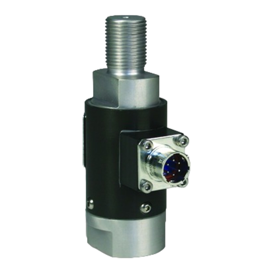
ROD END LOAD CELL OPERATION MANUAL 3.1 Dimensions 1.0 INTRODUCTION Rod end load cells manufactured by PCB Load & Torque, Inc. are designed for integration into tension/compression measurement applications such as process automation, quality assurance, and production monitoring. Standard 3/4”-16 and 1”-14 male/female threads facilitate ease of installation. -
Page 7: Electrical Installation
ROD END LOAD CELL OPERATION MANUAL 5.3 Cable & Grounding Considerations 5.0 ELECTRICAL INSTALLATION Proper grounding and shielding is required to prevent Table 4 - Electrical Connections electrical noise in strain gage load cell measuring systems. The cable must be shielded twisted pairs with a drain wire. Load Cell Receptacle: PT02E-10-6P Mating Connector:... - Page 8 ROD END LOAD CELL OPERATION MANUAL 6.1.1 Measured Output 7.0 SHUNT CALIBRATION DESCRIPTION The applied load starting at zero is measured in five Shunt calibration is used to simulate a known tension or increments to full scale. Output (mV/V) is measured at each compression load on a load cell.
-
Page 9: Maintenance
ROD END LOAD CELL OPERATION MANUAL 8.0 MAINTENANCE 10. Keep a record of your observations, correct problems, or contact PCB factory for assistance. Routine maintenance of the rod end load cell should include cleaning the electrical connectors, housings, and mounting surfaces with solutions and techniques that will not harm the 10.0 CALIBRATION / REPAIR SERVICES physical material of construction. - Page 10 Mounting Thread No English Equivalent M20 x 1.50 Female PCB Load & Torque Mounting Thread No English Equivalent M20 x 1.50 Male A Division of PCB Piezotronics Cover Material Anodized Aluminum Anodized Aluminum 24350 Indoplex Circle Sensing Element Strain Gage...
- Page 11 PCB Load & Torque Inc. claims proprietary rights in REVISIONS the information disclosed hereon. Neither it nor any reproduction thereof will be disclosed to others without DESCRIPTION the written consent of PCB Load and Torque Inc. ADDED CHART FOR M1380 SERIES - 04.26.18, PTE 48167 .50 [12.7] .50 [12.7]...
Need help?
Do you have a question about the M1380-02A and is the answer not in the manual?
Questions and answers