Sign In
Upload
Download
Table of Contents
Contents
Add to my manuals
Delete from my manuals
Share
URL of this page:
HTML Link:
Bookmark this page
Add
Manual will be automatically added to "My Manuals"
Print this page
×
Bookmark added
×
Added to my manuals
Manuals
Brands
CF MOTO Manuals
Motorcycle
700CL-X Heritage
Owner's manual
CF MOTO 700CL-X Heritage Owner's Manual
Hide thumbs
Also See for 700CL-X Heritage
:
Owner's manual
(142 pages)
1
Table Of Contents
2
3
4
5
6
7
8
9
10
11
12
13
14
15
16
17
18
19
20
21
22
23
24
25
26
27
28
29
30
31
32
33
34
35
36
37
38
39
40
41
42
43
44
45
46
47
48
49
50
51
52
53
54
55
56
57
58
59
60
61
62
63
64
65
66
67
68
69
70
71
72
73
74
75
76
77
78
79
80
81
82
83
84
85
86
87
88
89
90
91
92
93
94
95
96
97
98
99
100
101
102
103
104
105
106
107
108
109
110
111
112
113
114
115
116
117
118
119
120
121
122
123
124
125
126
page
of
126
Go
/
126
Contents
Table of Contents
Bookmarks
Table of Contents
Table of Contents
Foreword
E VAP System (Evaporative Emission Control System)
Catalytic Converter
Introduction
VIN and Engine Serial Number
Specifications
Operator Safety
General Safety Precautions
Owner Responsibilities
Safe Riding Gear
Potential Hazard Warnings
Heritage Vehicle View
Rear Left View
Front Right View
Controls and Features
Clutch Lever
Front Hand Brake Lever
Handlebar Switch, LH
Handlebar Switch, RH
Electronic Throttle Assy
Locks
Gear Shift Lever
Rear Brake Lever
Side Stand
Passenger Handhold and Footrest
Instrument
Instrument Indicators
Instrument Display
Instrument Navigation / Settings / Adjustments
Operating Your Vehicle
Break-In Period
Daily Safety Inspection
Starting
Starting off
Shifting, Riding
Brake
Parking
Safety Operation
Safe Riding Technique
Additional Cautions for High Speed Operation
Maintenance
Severe Use Definition
Key Points of Lubrication Schedule
Break-In Maintenance Schedule
Periodic Maintenance Schedule
Clutch Lever Freeplay
Took Kit
Fuel System
Fuel Tank
Fuel Requirement
Octane Rating (RON)
Engine Assy
Engine Oil Level Inspection
Change Engine Oil and Oil Filter
Engine Oil Capacity
Spark Plug
Air Intake and Exhaust System
Fuel & Exhaust Detecting System
Air Intake Valve
Valve Clearance
Air Filter
Cooling System
Radiator and Cooling Fan
Radiator Hoses
Coolant
Coolant Level Inspection
Coolant Filling
Tire and Chain
Tire Specification
Tire Payload
Tire Friction
Drive Chain Inspection
Chain Tension Adjustment
Brake System
Front Brake Lever Inspection
Rear Brake Pedal Inspection
Brake Fluid Level Inspection
Adding Brake Fluid
Brake Disc Inspection
Brake Caliper Inspection
Anti-Lock Braking System (ABS)
Shock Absorber
Shock Absorber Inspection
Rear Shock Absorber Adjustment
Front Shock Absorber Adjustment
Preload Adjustment
Electrical System and Light Signal
Battery
Light
Fuse
Catalytic Converter
Fuel Evaporation System
Motorcycle Cleaning and Storage
General Precautions
Washing Vehicle
Protect the Surface
Windshield and Other Plastic
Chrome and Aluminum
Preparation for Storage
Advertisement
Quick Links
1
Specifications
2
Maintenance
3
Tire and Chain
4
Battery
Download this manual
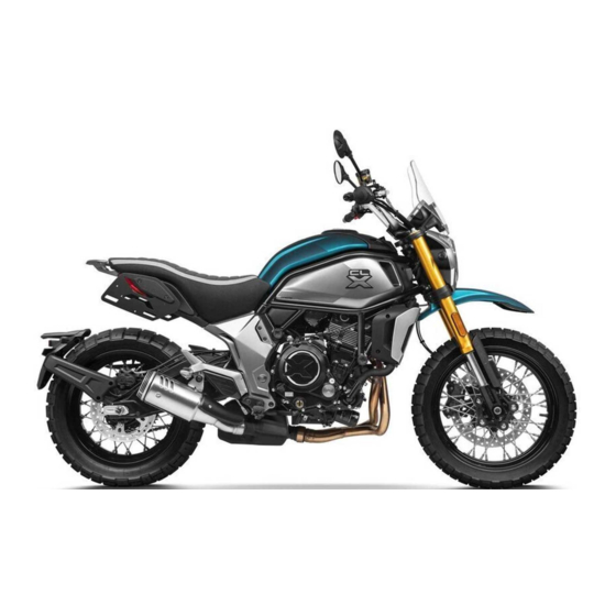
700CL-X
CF700-2
Owner's Manual
READ THIS MANUAL CAREFULLY
It contains important safety information.
This ROV should not be ridden by anyone under 18 years of age.
Passenger under 12 are prohibited.
Heritage
Table of
Contents
Previous
Page
Next
Page
1
2
3
4
5
Advertisement
Table of Contents
Need help?
Do you have a question about the 700CL-X Heritage and is the answer not in the manual?
Ask a question
Questions and answers
Subscribe to Our Youtube Channel
Related Manuals for CF MOTO 700CL-X Heritage
Motorcycle CF MOTO 700CL-X Owner's Manual
(142 pages)
Motorcycle CF MOTO 700CL-X Sport Owner's Manual
(112 pages)
Motorcycle CF MOTO 150NK Owner's Manual
(67 pages)
Motorcycle CF MOTO 650GT Owner's Manual
(102 pages)
Motorcycle CF MOTO 400NK Owner's Manual
(142 pages)
Motorcycle CF MOTO 450NK Owner's Manual
(162 pages)
Motorcycle CF MOTO CF400-A 2017 Service Manual
(443 pages)
Motorcycle CF MOTO 450MT 2023 Owner's Manual
(165 pages)
Motorcycle CF MOTO 450SR Owner's Manual
(141 pages)
Motorcycle CF MOTO 450SR S Owner's Manual
(151 pages)
Motorcycle CF MOTO 250CL-X Owner's Manual
(121 pages)
Motorcycle CF MOTO PAPIO Owner's Manual
(122 pages)
Motorcycle CF MOTO 800MT Owner's Manual
(208 pages)
Motorcycle CF MOTO 250NK Owner's Manual
(159 pages)
Motorcycle CF MOTO 250SR Owner's Manual
(161 pages)
This manual is also suitable for:
Cf700-2
Table of Contents
Save PDF
Print
Rename the bookmark
Delete bookmark?
Delete from my manuals?
Login
Sign In
OR
Sign in with Facebook
Sign in with Google
Upload manual
Upload from disk
Upload from URL


Need help?
Do you have a question about the 700CL-X Heritage and is the answer not in the manual?
Questions and answers