Advertisement
Quick Links
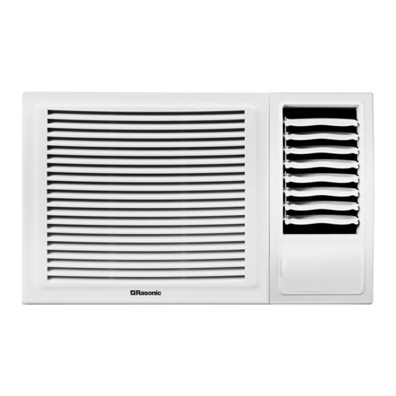
R32 WINDOW-TYPE AIR CONDITIONER(COOLING ONLY)
Operation Manual &
Installation Manual
Model:
RC-X7R
RC-X9R
RC-X12R
RC-X18R
IMPORTANT NOTE:
This appliance is using R32 mildly flammable refrigerant.
Read this manual carefully before installing or operating.
.
Make sure to save this manual for future reference.
Please check the applicable models, technical
data from the nameplate pasted on the unit.
Advertisement


Need help?
Do you have a question about the RC-X7R and is the answer not in the manual?
Questions and answers