Advertisement
Quick Links
DESCRIPTION
Demonstration circuit 2603A-A features the
®
LTM
4650AEY-1, the high efficiency, high density, dual
25A, single 50A switch mode step-down power mod-
ule regulator. The input voltage is from 4.5V to 16V.
The output voltage is programmable from 0.6V to 5.5V.
DC2603A-A can deliver 25A maximum current from each
channel. The board designs with minimum components to
demonstrate this high efficiency, high density µModule
As explained in the data sheet, output current derating is
necessary for certain V
IN
The board operates in continuous conduction mode in
heavy load conditions. For high efficiency at low load
currents, the MODE jumper (JP1) selects pulse-skipping
mode for noise sensitive applications or Burst Mode
operation in less noise sensitive applications. Two out-
puts can be connected in parallel for a single 50A out-
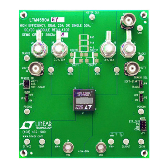
BOARD PHOTO
, V
, and thermal conditions.
OUT
Figure 1. LTM4650A/DC2603A-A Demo Board
DEMO MANUAL DC2603A-A
Dual 25A or Single 50A
DC/DC μModule Regulator
put solution with optional jumper resistors. The board
allows the user to program how its output ramps up and
down through the TRACK/SS pin. The output can be set
up to either coincidentally or ratiometrically track with
another supply's output. Remote output voltage sens-
ing is available for improved output voltage regulation at
the load point. These features and the availability of the
®
.
LTM4650AEY in a compact 16mm × 16mm × 5.01mm
BGA package make it ideal for use in many high-density
point-of-load applications. The
must be read in conjunction with this demo manual for
working on or modifying the demo circuit DC2603A-A.
Design files for this circuit board are available at
®
http://www.linear.com/demo/DC2603A-A
L, LT, LTC, LTM, BUrst Mode, µModule, Linear Technology and the Linear logo are registered
trademarks of Analog Devices, Inc. All other trademarks are the property of their respective
owners.
LTM4650AEY
LTM4650A
data sheet
dc2603aaf
1
Advertisement

Related Manuals for Linear Technology DC2603A-A


Summary of Contents for Linear Technology DC2603A-A
- Page 1 Two out- L, LT, LTC, LTM, BUrst Mode, µModule, Linear Technology and the Linear logo are registered puts can be connected in parallel for a single 50A out- trademarks of Analog Devices, Inc. All other trademarks are the property of their respective owners.
-
Page 2: Quick Start Procedure
8. (Optional) LTM4650A-1 can be configured for a 2-phase voltage regulation, output voltage ripple, efficiency and single output at up to 50A on DC2603A-A. Install 0Ω resis- other parameters. Output ripple can be measured at J1 tors on R14, R17, R28, R39, R43, R44, R45 and remove and J2 with BNC cables.50Ω... - Page 3 DEMO MANUAL DC2603A-A QUICK START PROCEDURE + – – LOAD2 (0~25A) LOAD1 (0~25A) + – – OUT2 OUT1 dc2603aaf 4.5V-16V – + – + – Figure 2. Test Setup of DC2603A-A dc2603aaf...
- Page 4 DEMO MANUAL DC2603A-A QUICK START PROCEDURE Efficiency vs Load Current at V = 1.5V, f = 600kHz 94.0 93.1 93.0 92.2 90.7 90.3 91.8 91.6 90.9 90.4 88.9 =12V 83.4 OUTPUT LOAD CURRENT (A) Figure 3. Measured Efficiency on Channel 1 (V = 1.5V, f...
- Page 5 DEMO MANUAL DC2603A-A QUICK START PROCEDURE 1.5V Output (20MHz BW) [20mV/Div] 12.5A-18.75A Load Step Figure 5. Measured Channel 1 12.5A-18.75A Load Transient (V = 12V, V = 1.5V) OUT1 3.3V Output (20MHz BW) [50mV/Div] 12.5A-18.75A Load Step Figure 6. Measured Channel 2 12.5A-18.75A Load Transient (V = 12V, V = 3.3V)
- Page 6 DEMO MANUAL DC2603A-A QUICK START PROCEDURE Figure 7. Measured Output Voltage Ripple at 12V Voltage Input, 1.5V/25A, f = 600kHz, Measured Across C Using 1× Probe OUT6 Figure 8. Measured Output Voltage Ripple at 12V Voltage Input, 3.3V/25A, f = 600kHz, Measured Across C Using 1×...
- Page 7 DEMO MANUAL DC2603A-A QUICK START PROCEDURE Figure 9. Thermal Performance at V = 12V, V = 1.5V/25A, V = 3.3V/25A, f = 600kHz, T = 23 °C, No Forced Air Airflow OUT1 OUT2 dc2603aaf...
- Page 8 DEMO MANUAL DC2603A-A PARTS LIST ITEM REFERENCE PART DESCRIPTION MANUFACTURER/PART NUMBER Required Circuit Components CIN1 CAP ., 330µF, ALUM, OS-CON, 25V, 20%, SMD PANASONIC, 25SVPF330M 10mm × 12.6mm, F12, SVPF Series CIN2,CIN3,CIN4,CIN5 CAP ., 22µF, X5R, 25V, 10%,1210 MURATA, GRM32ER61E226KE15L COUT2, COUT6, COUT13, CAP ., 100µF, X5R, 6.3V, 20%, 1210...
-
Page 9: Parts List
DEMO MANUAL DC2603A-A PARTS LIST ITEM REFERENCE PART DESCRIPTION MANUFACTURER/PART NUMBER R38, R43, R44, R45 RES., OPTION, 2512 Hardware: For Demo Board Only E1, E3, E4, E5, E6, E7, E8, E9, TEST POINT, TURRET, .094" MTG. HOLE MILL-MAX, 2501-2-00-80-00-00-07-0 E10, E12, E13, E14, E15, E16, E17, E18 CONN., HDR, MALE, 2 ×... - Page 10 DEMO MANUAL DC2603A-A SCHEMATIC DIAGRAM dc2603aaf...
-
Page 11: Schematic Diagram
Information furnished by Linear Technology Corporation is believed to be accurate and reliable. However, no responsibility is assumed for its use. Linear Technology Corporation makes no representa- tion that the interconnection of its circuits as described herein will not infringe on existing patent rights. - Page 12 Linear Technology Corporation (LTC) provides the enclosed product(s) under the following AS IS conditions: This demonstration board (DEMO BOARD) kit being sold or provided by Linear Technology is intended for use for ENGINEERING DEVELOPMENT OR EVALUATION PURPOSES ONLY and is not provided by LTC for commercial use. As such, the DEMO BOARD herein may not be complete in terms of required design-, marketing-, and/or manufacturing-related protective considerations, including but not limited to product safety measures typically found in finished commercial goods.
Need help?
Do you have a question about the DC2603A-A and is the answer not in the manual?
Questions and answers