Table of Contents
Advertisement
Quick Links
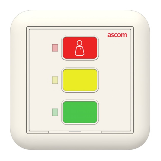
Customizable Button Module Installation Sheet
Description
The NUDM3-HE Customizable Button module is a wall-
mounted device that is suitable for general room
applications. The module connects to an active room bus
and is typically mounted near a door.
Module Connectors
The module includes two RJ-45 jacks for room bus
connections and DIP switches for room bus addressing.
Figure 1 shows the jacks and DIP switches on the back of
the module.
Figure 1: Module connections
Legend
(1) DIP switches for bus addressing
(2) Buzzer
(3) 2x RJ-45 connections to room bus
P/N PM000156A • Rev. 2 • ISS 19JUN2018
Model NUDM3-HE
Setting the Room Bus Address
The room bus address is a unique number assigned to a room
module when modules of the same type are attached to the
room bus.
If you do not use DIP switches to set the room bus address,
be sure all the DIP switches are in the OFF position on the
back of the module.
To set the DIP switches:
1. Set the DIP switches for the correct room bus address
(0...3), as shown in Figure 1, item 1.
2. Using a small screwdriver, gently slide the switch up for
"ON" or slide it down for "OFF."
Installation
Note: Before beginning the installation, ensure all the
necessary cables are available and are properly terminated.
RJ-45 connectors should be terminated in accordance with
the T568B or EIA 568B connection standard.
The module can mount to a backbox, or to a wall using a
surface-mounting spacer (NUSP1-HE).
To mount the module on a backbox or spacer:
1. When using a backbox, loosen the screws on the backbox
so that approximately 5mm extend out from the backbox
and the heads of the screws can pass through the keyhole
slots of the adapter plate.
-or-
When using a spacer, ensure it is properly mounted to the
wall and that the adapter screws are available.
2. Place the adapter (with the arrow facing up) over the
backbox and ensure that it is level.
© 2018 Ascom, Inc.
1 of 3
Advertisement
Table of Contents

Subscribe to Our Youtube Channel
Related Manuals for ASCOM NUDM3-HE


Summary of Contents for ASCOM NUDM3-HE
- Page 1 Note: Before beginning the installation, ensure all the necessary cables are available and are properly terminated. The NUDM3-HE Customizable Button module is a wall- RJ-45 connectors should be terminated in accordance with mounted device that is suitable for general room the T568B or EIA 568B connection standard.
- Page 2 -or- To make the connections to the module: When using a spacer, place the adapter over the spacer 1. Check the DIP switch settings to ensure that they are set ensuring that it fits inside the spacer’s housing. correctly. See Figure 1, item 1. 2.
- Page 3 Inserting Customized Button Labels Accessories for the module include Customizable Button Insert Kits (P/N NUCBK-HE and NUCBK-HK). Each kit contains a variety of color strips that easily insert into the module’s faceplate to cover the buttons and LEDs for a custom look. The kits include strips for one, two, or three button configurations.
Need help?
Do you have a question about the NUDM3-HE and is the answer not in the manual?
Questions and answers