Advertisement
Quick Links
Advertisement

Subscribe to Our Youtube Channel
Related Manuals for ASCOM NUBM3-HE


Summary of Contents for ASCOM NUBM3-HE
- Page 1 INSTALLATION GUIDE Bedside Module (NUBM3-HE)
- Page 2 INSTALLATION GUIDE Symbols Bedside Module (NUBM3-HE) Symbols Important Safety Information The Bedside Module (NUBM3–HE) Installation Guide contains important instructions when installing and maintaining the NUBM3–HE. To ensure a safe working environment during the installation and operation of the NUBM3–HE, the following safety symbols appear throughout this document to indicate dangerous conditions and important safety instructions.
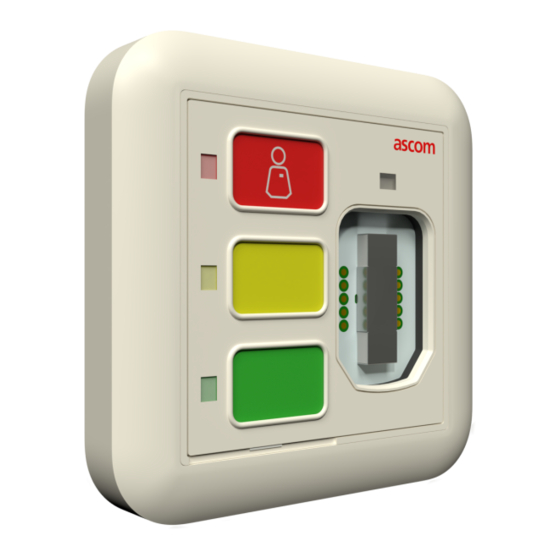
- Page 3 INSTALLATION GUIDE Bedside Module (NUBM3-HE) Description Description The Bedside module is a wall-mounted device that is suitable for general room applications. The module connects to an active room bus and is typically mounted near a bed. Packing list: • 1 x Bedside module NUBM3–HE...
- Page 4 INSTALLATION GUIDE Mounting Bedside Module (NUBM3-HE) Mounting The base of the module mounts directly onto flat walls or ceiling surfaces. Caution: To prevent a fire hazard because of dust buildup inside the module, regular inspection and/or cleaning of the module is required.
- Page 5 INSTALLATION GUIDE Bedside Module (NUBM3-HE) Mounting Using the spacer as a template, mark two holes for the screws using the outer fitting holes located in the corners of the spacer. Remove the spacer and drill screw holes for the screws that will be used, such as wood, concrete, or drywall screws, or screws with anchors.
-
Page 6: Module Connectors
INSTALLATION GUIDE Bedside Module (NUBM3-HE) Module Connectors Module Connectors The module includes two RJ45 jacks for room bus connections, a connector for light relays, a connector for the NUBM3X-HE extension module, and DIP switches for room bus addressing. Figure 1 shows the connectors and DIP switches on the back of the module. - Page 7 INSTALLATION GUIDE Bedside Module (NUBM3-HE) Connecting to light relays Connecting to light relays The NUBM3–HE offers two light connections: two relay circuits for switching external light sources that are operated via the handset connected to the module. Each relay circuit is suitable for switching an external bi-stable 24 volt DC relay. The maximum switching current for each relay must not exceed 0.2A at max.
- Page 8 INSTALLATION GUIDE Bedside Module (NUBM3-HE) Mount the NUBM3–HE Mount the NUBM3–HE Pull the room buses through the adapter plate and the frame. 8 Terminating the Room Bus RJ45 Connectors, page Insert the room buses into the RJ45 connectors on the rear side of the NUBM3–HE.
-
Page 9: Removing The Module
INSTALLATION GUIDE Bedside Module (NUBM3-HE) Removing the module Removing the module Removal of the NUBM3–HE from wall or ceiling. Remove the module: • Insert a small flat tipped screwdriver into the hole on the bottom of the frame (item 1). - Page 10 INSTALLATION GUIDE Terminating the Room Bus RJ45 Connectors Bedside Module (NUBM3-HE) Terminating the Room Bus RJ45 Connectors The NUBM3–HE includes two active room bus RJ45 sockets. Crimp the RJ45 connector(s) to the room bus cable(s) using the Ethernet T-568B termination color scheme. The following figure shows the correct pinout for terminating the active room bus cables.
- Page 11 INSTALLATION GUIDE Bedside Module (NUBM3-HE) Replacing the button insert Replacing the button insert Remove current button insert by gently pulling the small tab at the lower end of the insert with a small pair of pliers. Insert a new button insert from the lower end of the module. Make sure the insert fits completely in the membrane.
-
Page 12: Specifications
INSTALLATION GUIDE Specifications Bedside Module (NUBM3-HE) Specifications Wire/terminations Cat 5/5e/6/7, U/UTP Cat 6/7 cable will work electrically but may be too stiff for some back boxes. Compatible electrical boxes (metal • EU box (or equivalent) Single backbox with mounting holes or plastic) 60mm (2.36in.) -
Page 13: Document History
INSTALLATION GUIDE Bedside Module (NUBM3-HE) Document History Document History Description Version Date 28 February First released version A 2022 TD 93505EN / 28 February 2022 / Ver. A... - Page 14 Ascom (Sweden) AB Grimbodalen 2 SE–417 49 Göteborg Sweden Phone +46 31 55 93 00 www.ascom.com...
Need help?
Do you have a question about the NUBM3-HE and is the answer not in the manual?
Questions and answers