
Related Manuals for Vox Ignis Lexicomm ViLX-228


Summary of Contents for Vox Ignis Lexicomm ViLX-228
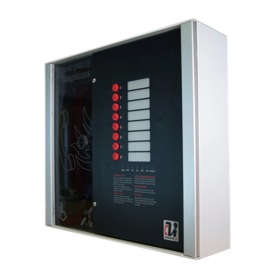
- Page 1 Lexicomm ViLX-228 EVCS Master Station Installation and Commissioning Manual Version 6 September 2017 www.acornfiresecurity.com...
-
Page 2: Table Of Contents
www.acornfiresecurity.com Table of Contents 1. Introduction ..........................3 1.1 What is an Emergency Voice Communication System .............. 3 1.2 Suitability ..........................3 2. Product Overview ........................3 3. Important Safety Information ...................... 4 4. Unpacking the Unit ........................5 5. Installation ..........................6 5.1 Connecting the ViLX-228 Master Station ................. -
Page 3: Introduction
At sports venues and similar complexes, where it will assist stewards in controlling the evacuation of the area in an emergency. The Lexicomm ViLX-228 Emergency Voice Communications System (EVCS) is designed to fully comply with BS5839 Part 9:2011 for use as a Fire Telephone system, Disabled Refuge Call system or as a combined system when both Fire Telephones and Disabled Refuge Points are required. -
Page 4: Important Safety Information
www.acornfiresecurity.com 3. Important Safety Information This Equipment must only be installed and maintained by a suitably skilled and competent person. This Equipment is defined as Class 1 in EN60065 (Low Voltage Directive) and must be EARTHED. Caution Indoor Use Only Shock Hazard- Warning Isolate Before Opening... -
Page 5: Unpacking The Unit
1 number Battery lead. • If there are any items missing, please contact your supplier or Vox Ignis Limited, quoting the unit serial number and the name on the packing list enclosed, so the situation can be rectified. Page 5 of 24 Document PViLX228 7001-06 Rev 6 2017 www.acornfiresecurity.com... -
Page 6: Installation
www.acornfiresecurity.com 5. Installation Prior to mounting the ViLX-228 Master Station, it should be decided if the field wiring is to be run on the surface or concealed. . There are 14 knockouts on the top and 2 slotted entries with a dedicated mains supply entry at the rear. -
Page 7: Connecting The Vilx-228 Master Station
www.acornfiresecurity.com 5.1 Connecting the ViLX-228 Master Station To comply with EMC (Electro Magnetic Compatibility) regulations and to reduce the risk of electrical interference in the system wiring, the use of fire-resistant screened cables is recommended throughout the installation. All wiring should come into the enclosure via the knockouts provided, and be fixed tidily to the relevant terminals. -
Page 8: Vilx-228 Master Station Wiring
www.acornfiresecurity.com 5.4.1 ViLX-228 Master Station Wiring The wiring for a ViLX-228 Master Station is shown in the schematic below. Page 8 of 24 Document PViLX228 7001-06 Rev 6 2017 www.acornfiresecurity.com... -
Page 9: Vilx-228 Master/Repeater Stations Wiring In Ring
www.acornfiresecurity.com 5.4.2 ViLX-228 Master/Repeater Stations wiring in ring If two ViLX-228 Stations are wired in Master/Repeater format, with the outstations shared between both the Master Station and the Repeater Station, the ViLX-228 system has to be wired as a ring, with each outstation connected via a radial circuit to either the Master Station or Repeater Station, as shown in the schematic below. -
Page 10: Mains Connection
www.acornfiresecurity.com 5.5 Mains Connection >0.75mm <2.5mm ViLX-228 M a in UNITY Master Station Distr ib u tio n Bo a r d > 3 m m Each ViLX-228 Master/Repeater Station requires a 3A spur, returning to a breaker clearly marked “EVCS DO NOT TURN OFF”. -
Page 11: Type A Outstation
www.acornfiresecurity.com 5.7.1 Type A outstation Note: The Earth screen should be sleeved and connected to the terminal block in the controller, and the earth stud in the Type A outstation. 5.7.2 Type B outstation Note: The Earth screen should be sleeved and connected to the terminal block in the controller, and the earth connection in the metal back box (if a plastic back-box is used cut the earth back and insulate at the outstation) 5.7.3 ACA Accessible Toilet Kit... -
Page 12: Auxiliary Connections
www.acornfiresecurity.com 5.8 Auxiliary Connections The ViLX-228 Master Station has three auxiliary connections: Fault is a normally closed volt free relay (30V DC 1A) which OPENS on any fault, including loss of power. In Use is a normally open volt free relay (30V DC 1A) connection which closes when any outstation is operated, see Remote Signal Display section 7.6 switch settings for further information. -
Page 13: Set Up Procedure
www.acornfiresecurity.com 6. Set up procedure The ViLX-228 Master Station has various site configurations which are configured using the dipswitch located on the rear of the Display PCB. 6.1 ViLX-228 Master Station Display PCB Dipswitch Settings Line Line Line Line Network Reserved Remarks 1&2... -
Page 14: Adding A Line Card
www.acornfiresecurity.com Exchange PCB Diagram- 6.2 Adding a Line Card The ViLX-228 Master Station is supplied with at least one number Line Card. There are 2 lines per Line Card. Before adding a Line Card, ensure that the ViLX-228 Master Station is not powered. If the ViLX-228 Master Station is powered, then power down the ViLX-228 Master Station (see 5.10). -
Page 15: Vilx-228 Master Station Exchange Pcb Dipswitch Settings
www.acornfiresecurity.com ViLX-228 Master Station Exchange PCB Dipswitch Settings The ViLX-228 Master Station can be integrated with a ViLX-TMS Master Station to form part of a Lexicomm site wide network where the ViLX-228 Master Station provides a local control and wiring position reporting back to the ViLX-TMS. -
Page 16: System Menus
www.acornfiresecurity.com 7. System Menus 7.1 Fault Accept Before accepting faults, the fault must be noted in the log book, along with the time the fault was reported. To accept the fault, enter either the access level 2 (code: 1664) or access level 3 (code: 1812) menu, then press zone button 1. -
Page 17: Engineer Walk Test
www.acornfiresecurity.com 7.5 Engineer Walk Test The engineer walk test mode enables all connected outstations, including “Assist Call”, to be tested for correct operation by a single engineer without needing to return to the Master Station to reset the calls, until complete. Enter the access level 3 engineer code (1812) then press zone button 5. -
Page 18: In Use Relay Options
www.acornfiresecurity.com 7.7 In Use Relay Options The in use relay has programmable functions which can work in tandem with the delay timer described in 7.6. These functions can provide a relay output as described in the table below: These relay functions can be useful for providing an output of specific system operation of EVC, Assist Call or both. -
Page 19: Acknowledging "Assist Call" Alarms
www.acornfiresecurity.com 8.6 Acknowledging “Assist Call” alarms When an “Assist Call” goes into alarm, the appropriate zone LED will flash blue, and a two-tone buzzer sounds to indicate that an “Assist Call” alarm has been operated. To acknowledge the alarm, press the corresponding zone button, and the blue LED will illuminate continuously with an intermittent buzzer tone every 15 seconds. -
Page 20: Power Supply And Cpu Indicator Summary
www.acornfiresecurity.com 9.2 Power supply and CPU indicator Summary General Description Mains OK Flash Flash Mains failure Battery OK Flash Flash Battery open circuit Flash Battery short circuit Flash Flash Battery high impedance Flash PSU processor fail ... -
Page 21: Commissioning Procedure
www.acornfiresecurity.com 10. Commissioning procedure The commissioning should be carried out by a competent person who has a basic knowledge and understanding of the design and installation sections of BS5839 part 9:2011, and has access to the specification of the project. The 500v insulation tests should have been carried out by the installer and the results made available to the commissioning engineer. -
Page 22: Outstation Zone Template
www.acornfiresecurity.com 12. Outstation zone template There is space to the right of each outstation zone indicator to name the location of the outstation. At the rear of the display door there is a slot located in the centre above the display PCB; the outstation zone template can be inserted here. - Page 23 www.acornfiresecurity.com Notes Page 23 of 24 Document PViLX228 7001-06 Rev 6 2017 www.acornfiresecurity.com...
-
Page 24: Technical Specification
www.acornfiresecurity.com 13. Technical Specification Product Code ViLX-228 Power Supply and Charger AC Input 230Vac+- 10% 50/60Hz Internal power supply 12Vdc nominal Supply and battery Monitored open, Short, Fuses Protection Deep discharge, Short, Thermals Temperature compensation Battery information Space for Up to 1x 12V 7AH VRSLA Mains fuse 1A HRC(T) Battery fuse...
Need help?
Do you have a question about the Lexicomm ViLX-228 and is the answer not in the manual?
Questions and answers