Table of Contents
Advertisement
Quick Links
Advertisement
Table of Contents

Related Manuals for Advantech TS-206


Summary of Contents for Advantech TS-206
- Page 1 User Manual TS-206 In-Vehicle Smart Fleet Management Computer...
- Page 2 Please download the latest English user manual and drivers on website: https://www.advantech.tw/products/1-flnuyz/ts-206/mod_fbd3dc60-12e1-41f6-978b- d74bdd128da4 Please disregard the printed Chinese copy of the user manual if the product is not to be sold and/or installed in China. 甲類警語: 警告使用者:這是甲類資訊產品,在居住的環境中使用時, 可能會造成射 頻干擾,在這種情況下,使用者會被要求採取某些適當對策。 TS-206 User Manual...
- Page 3 No part of this manual may be reproduced, copied, translated, or transmitted in any form or by any means without the prior written permission of Advantech Co., Ltd. The information provided in this manual is intended to be accurate and reliable.
- Page 4 This product has passed the CE test for environmental specifications when shielded cables are used for external wiring. We recommend the use of shielded cables. This type of cable is available from Advantech. Please contact your local supplier for ordering information.
- Page 5 Document Feedback To assist us with improving this manual, we welcome all comments and constructive criticism. Please send all feedback in writing to support@advantech.com. Packing List Before system installation, check that the items listed below are included and in good condition.
- Page 6 Sensitive electronic components can be damaged by sudden power surges. CAUTION: Always ground yourself to remove any static charge before touching the motherboard, backplane, or add-on cards. Modern electronic devices are very sensitive to static electric charges. As a safety precaution, use a grounding TS-206 User Manual...
- Page 7 La température de fonctionnement est de - 20 ° C à 60 ° C. ATTENTION: L'ordinateur est fourni avec un circuit d'horloge en temps réel ali- menté par batterie. Il y a un risque d'explosion si la batterie n'est pas remplacée TS-206 User Manual...
- Page 8 (ex. Vis) fournis avec la boîte d'accessoires. ATTENTION: Tout composant non vérifié qui pourrait causer des dommages inattendus. Pour garantir une installation correcte, s'il vous plaît utiliser toujours les composants (vis ex.) Fournis avec la boîte d'accessoires. TS-206 User Manual viii...
-
Page 9: Table Of Contents
Figure 3.1 Top side of main board..........16 Figure 3.2 Bottom side of main board........17 3.1.2 I/O Board (TS-206-U4A1E Only) ..........17 Figure 3.3 Top side of I/O board..........17 Figure 3.4 Bottom side of I/O board........... 18 3.1.3 I/O board (TS-206-U6A1E Only).......... - Page 10 Chapter Assignments....... 27 TS-206-U4A1E I/O Connectors .............. 28 4.1.1 TS-206-U4A1E Front I/O View ........... 28 4.1.2 TS-206-U4A1E Rear I/O View ............ 28 TS-206-U4A1E I/O Pin Definition............29 4.2.1 VGA Connector................29 Figure 4.1 VGA Connector ............29 Table 4.1: VGA Connector Pin Assignments ......29 4.2.2...
- Page 11 Figure 5.26GT – Power Management Control......69 Figure 5.27PCH-IO Configuration..........70 Figure 5.28PCI Express Configuration ........71 Figure 5.29PCI Express Root Port 1 .......... 72 Figure 5.30PCI Express Root Port 2 .......... 73 Figure 5.31PCI Express Root Port 5 .......... 74 TS-206 User Manual...
- Page 12 Security..................80 Figure 5.37Security ..............80 5.2.5 Boot .................... 81 Figure 5.38Boot ................81 5.2.6 Save & Exit ................. 82 Figure 5.39Save & Exit............... 82 Appendix A A WDT Sample Code ......85 Watchdog Timer Sample Code............... 86 TS-206 User Manual...
-
Page 13: Chapter 1 General Introduction
Chapter General Introduction This chapter gives background information on TS-206 series. -
Page 14: Introduction
Introduction TS-206 is an industrial grade dual core mobile device for in-vehicle computer and in- vehicle NVR solutions. TS-206 supports Full-HD NVR solutions and is fully integrated with certified hardware and intelligent management software. TS-206 has integrated in-vehicle power (ISO- 7637-2), conforms to in-vehicle certifications (E-Mark, IEC-60721-3-55M3), and has specially-developed vehicle software SDK and APIs for in-vehicle applications. -
Page 15: Features
2.5" drive bay: 1 x removable 2.5" drive bay (Max 9.5 mm height) – mSATA: 1x full size mSATA storage Serial ports: TS-206-U4A1E: 2 x RS-232/422/485 ports w/3 KV isolation (sup- port auto flow control, jumper selectable) TS-206 User Manual... - Page 16 Universal serial bus (USB) port: 2 x USB 2.0 & 2 x USB3.0 LAN port: 2 x Giga LAN 10/100/1000 Mbps Power over Ethernet, POE (TS-206-U6A1E only): Supports 4 x 10/100 Mbps – 4 ports full-load, IEEE802.3af Class 2 (7 Watt) –...
-
Page 17: Dimensions
Dimensions Figure 1.1 TS-206 dimensions TS-206 User Manual... - Page 18 TS-206 User Manual...
-
Page 19: Chapter 2 Hardware Installation
Chapter Hardware Installation This chapter introduces the instal- lation of TS-206 Hardware. -
Page 20: Overview Of Hardware Installation & Upgrading
Take care in order to avoid injury or damage to the equipment. Installing Memory Remove 9 screws in total to install memory on the top side of the board. (screws: 4pcs on top and 5pcs on side of the top cover) TS-206 User Manual... -
Page 21: Installing Storage
Installing storage 2.3.1 Installing 2.5" SSD or HDD 2.3.2 Installing mSATA Storage Remove 6 screws on the bottom cover. TS-206 User Manual... - Page 22 Remove 2.5" drive bay and Insert full size mSATA storage in the place marked. TS-206 User Manual...
-
Page 23: Installing Optional Modules
Installing Optional Modules 2.4.1 Installing WLAN module Remove 6 screws on the bottom cover. TS-206 User Manual... - Page 24 Remove the 2.5" drive bay and Insert the half size WLAN module in the place marked. TS-206 User Manual...
-
Page 25: Installing Wwan Module
2.4.2 Installing WWAN module Remove 6 screws on the bottom cover. Insert the full size WWAN module in the place marked. TS-206 User Manual... - Page 26 TS-206 User Manual...
-
Page 27: Chapter 3 Jumper And Switch Settings
Chapter Jumper and Switch Settings This chapter explains how to set up TS-206 Series hardware, including instructions on setting jumpers and connecting peripher- als, and how to set switches and read indicators. Be sure to read all the safety pre- cautions before beginning the installation procedure. -
Page 28: Setting Jumpers And Switches
An arrow is used on the motherboard to indicate the first pin of each jumper. 3.1.1 Main Board Figure 3.1 Top side of main board TS-206 User Manual... -
Page 29: I/O Board (Ts-206-U4A1E Only)
Figure 3.2 Bottom side of main board 3.1.2 I/O Board (TS-206-U4A1E Only) Figure 3.3 Top side of I/O board TS-206 User Manual... -
Page 30: I/O Board (Ts-206-U6A1E Only)
Figure 3.4 Bottom side of I/O board 3.1.3 I/O board (TS-206-U6A1E Only) Figure 3.5 Bottom side of I/O board TS-206 User Manual... -
Page 31: Power Board
3.2.1 Main Board Jumpers & Switches Auto Power On Setting Clear CMOS 3.2.2 I/O Board (TS-206-U4A1E Only) Jumper List RS232/422/485 Jumper Setting - COM2 RS232/422/485 Jumper Setting - COM1 3G Voice audio - PCM data in/out swap SW1&SW4 3G/4G module Power Selection SW3&SW5... -
Page 32: I/O Board (Ts-206-U6A1E Only)
3.2.3 I/O Board (TS-206-U6A1E Only) Jumper List WWAN voice audio - PCM data in/out swap SW1&SW4 3G/4G module Power Selection SW3&SW5 3G/4G module Power Selection 3.2.4 Power Board Jumper List Power Ignition HW Setting Jumper Settings 3.3.1 Main Board 3.3.1.1 Auto Power On Setting (J2) Table 3.1: Auto Power On Setting (J2) -
Page 33: I/O Board (Ts-206-U4A1E Only)
3.3.2 I/O Board (TS-206-U4A1E Only) 3.3.2.1 RS232/422/485 Jumper Setting - COM1 (JP2) Table 3.3: RS232/422/485 Setting Setting Function (1-3), (4-6) * RS-232 (1-3), (2-4) RS-422 (3-5), (2-4) RS-485 3.3.2.2 RS232/422/485 Jumper Setting - COM2 (JP1) Table 3.4: RS232/422/485 Setting Setting... - Page 34 1(On), 2(Off), 3(On), 4(On) 1(Off), 2(Off) 3.8V 1(Off), 2(On), 3(Off), 4(Off) 3.3.2.5 3G/4G module Power Selection-miniPCIE2 (SW3&SW5) Table 3.7: WWAN Module Power Selection Laction Setting Function 1(Off), 2(Off) 3.3V 1(On), 2(Off), 3(On), 4(On) 1(Off), 2(Off) 3.8V 1(Off), 2(On), 3(Off), 4(Off) TS-206 User Manual...
-
Page 35: I/O Board (Ts-206-U6A1E Only)
3.3.3 I/O Board (TS-206-U6A1E Only) 3.3.3.1 WWAN voice audio - PCM data in/out swap (JP1) (1-3), (4-6) * (1-3), (2-4) Table 3.8: 3G Voice Audio -PCM Data In/Out Swap Setting Function (1-3), (4-6) * PCM_IN → PCMA_OUT; PCM_OUT → PCMA → IN (3-5),(2-4) PCM_IN →... - Page 36 3.3.3.3 3G/4G module Power Selection-miniPCIE2 (SW3&SW5) Table 3.10: WWAN Module Power Selection Laction Setting Function 1(Off), 2(Off) 3.3V 1(On), 2(Off), 3(On), 4(On) 1(Off), 2(Off) 1(Off), 2(On), 3(Off), 4(Off) TS-206 User Manual...
-
Page 37: Power Board
3.3.4 Power Board 3.3.4.1 Power Ignition HW Setting (SW1_1-3) Table 3.11: Power Ignition HW Setting Setting Function Ignition on Timer Ignition delay off timer Ignition hard off timer Off* Off* Off* TS-206 User Manual... - Page 38 3.3.4.2 Power Ignition SW/HW Setting (SW1_4) Table 3.12: Power Ignition SW/HW Setting Selection Setting Function Off* Power Ignition SW setting Power Ignition HW set TS-206 User Manual...
-
Page 39: Chapter 4 Pin Assignments
Chapter Pin Assignments This chapter explains Pin Assign- ments of TS-206 Series. -
Page 40: Ts-206-U4A1E I/O Connectors
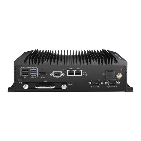
TS-206-U4A1E I/O Connectors 4.1.1 TS-206-U4A1E Front I/O View 4.1.2 TS-206-U4A1E Rear I/O View TS-206 User Manual... -
Page 41: Ts-206-U4A1E I/O Pin Definition
TS-206-U4A1E I/O Pin Definition 4.2.1 VGA Connector The TS-206 provides a high resolution VGA interface connected by a D-sub 15- pin connector to support a VGA CRT monitor. It supports display resolution of up to 1920 x 1200 with 60 Hz. -
Page 42: Usb Connector
4.2.2 USB Connector The TS-206 provides up to four USB interface connectors - 2 x USB 2.0 & 2 x USB 3.0, which give complete Plug & Play. The USB interface is compliant with USB UHCI, Rev. 2.0 & 3.0. The USB interface supports Plug and Play, which enables you to connect or disconnect a device whenever you want, without turning off the com- puter. -
Page 43: Hdmi Connector
DP_PWR 4.2.5 DIO Connector TS-206 offers an 8-bit phoenix type DIO connector and two ground pin. 6 x DI & 2 x DO w/3 KV isolation. Connector Type: 10-pin screw terminal block (6 DI points, 2 DO points, GND) ... -
Page 44: Power Input Connector
4.2.6 Power Input Connector TS-206 comes with 3-pin Pheonix type power input connector for 9 ~ 36 V input. Figure 4.6 Power Input Connector 4.2.7 COM Connector TS-206-U4A1E provides two D-sub 9-pin connectors, which offers 2 x RS-232/422/ 485 serial communication ports w/3 KV isolation. (Jumper setting selectable). -
Page 45: System Audio Connector
4.2.8 System Audio Connector TS-206 offers stereo audio ports via phone jack connector of Line-out, Mic-in & Line- in. The audio chip controller is by Realtek ALC888, High Definition Audio. Figure 4.8 System Audio Connector Table 4.6: Audio Connector Pin Assignments... -
Page 46: Optional I/O
2 x CANBus 2 x CANBus 4.2.11 Power Input Mode TS-206 provides two power input modes. One is P and the other one is V. P means for power adapter; V means for in-vehicle purpose. Figure 4.10 Power Input Mode 4.2.12... -
Page 47: Ts-206-U6A1E I/O Connectors
TS-206-U6A1E I/O Connectors 4.3.1 TS-206-U6A1E Front I/O View 4.3.2 TS-206-U6A1E Rear I/O View TS-206 User Manual... -
Page 48: Ts-206-U6A1E I/O Pin Definition
TS-206-U6A1E I/O Pin Definition 4.4.1 VGA Connector The TS-206 provides a high resolution VGA interface connected by a D-sub 15- pin connector to support a VGA CRT monitor. It supports display resolution of up to 1920 x 1200 with 60 Hz. -
Page 49: Usb Connector
4.4.2 USB Connector The TS-206 provides up to four USB interface connectors - 2 x USB 2.0 & 2 x USB 3.0, which give complete Plug & Play. The USB interface is compliant with USB UHCI, Rev. 2.0 & 3.0. The USB interface supports Plug and Play, which enables you to connect or disconnect a device whenever you want, without turning off the com- puter. -
Page 50: Ethernet Connector
RX+(10/100),BI_DB+(GHz) BI_DD+(GHz) BI_DC+(GHz) BI_DD-(GHz) 4.4.4 HDMI Connector TS-206 provides 1 x lockable HDMI port which resolution can support up to 4K at 24 Hz. Figure 4.17 HDMI Connector Table 4.11: HDMI/Display Port Connector Pin Assignments Signal Name Signal Name TMDS_Data2+/DP_Data0+ TMDS_Data2−/DP_Data0-... -
Page 51: Dio Connector
4.4.5 DIO Connector TS-206 offers an 8-bit phenix type DIO connector and two ground pin. 6 x DI & 2 x DO w/3 KV isolation. Connector Type: 10-pin screw terminal block (6 DI points, 2 DO points, GND) Input Voltage: 0 to 30 V at 25 Hz ... - Page 52 Unused 4.4.8 System Audio Connector TS-206 offers stereo audio ports by a phone jack connector of Line-out, Mic-in & Line-in. The audio chip controller is by Realtek ALC888, High Definition Audio. Figure 4.21 System Audio Connector Table 4.13: Audio Connector Pin Assignments...
- Page 53 2 x CANBus 4.4.11 Power Input Mode TS-206 provides two power input modes. One is P and the other one is V. P means for power adapter; V means for in-vehicle purpose. Figure 4.23 Power Input Mode TS-206 User Manual...
- Page 54 4.4.12 Power On/Off Button TS-206 comes with a Power On/Off button, that supports the dual function of Soft Power -On/Off (Instant off or Delay 4 Second), and Suspend. Figure 4.24 Power ON/OFF Button 4.4.13 Reset TS-206 comes with reset function for users to reset the unit if necessary.
- Page 55 Chapter BIOS settings This chapter introduces how to set BIOS configuration data.
- Page 56 AMIBIOS has been integrated into many motherboards for over a decade. With the AMIBIOS Setup program, you can modify BIOS settings and control the various sys- tem features. This chapter describes the basic navigation of the TS-206 BIOS setup screens.
- Page 57 Entering Setup Turn on the computer and then press <F2> or <DEL> to enter the Setup menu. 5.2.1 Main Setup When you first enter the BIOS Setup Utility, you will enter the Main setup screen. You can always return to the Main setup screen by selecting the Main tab. There are two Main Setup options.
- Page 58 5.2.2 Advanced BIOS Features Setup Select the Advanced tab from the TS-206 setup screen to enter the Advanced BIOS Setup screen. You can select any of the items in the left frame of the screen, such as CPU Configuration, to go to the sub menu for that item. You can display an Advanced BIOS Setup option by highlighting it using the <Arrow>...
- Page 59 5.2.2.1 ACPI Settings Figure 5.4 ACPI Settings Enable Hibernation Enables or Disables system ability to Hibernate (OS/S4 sleep state). ACPI Sleep State Select the highest ACPI sleep state the system will enter when the SUSPEND button is pressed. ASMB-816 User Manual...
- Page 60 5.2.2.2 AMT Configuration Figure 5.5 AMT Configuration Intel AMT Enable/Disable Intel Active Management Technology BIOS Extension. BIOS Hotkey Pressed Enable/Disable BIOS hotkey press. MEBx Selection Screen Enable/Disable MEBx selection screen. Hide Un-Configure ME Confirmation Prompt Hide Un-Configure ME without password Confirmation Prompt. MEBx Debug Message Output ...
- Page 61 5.2.2.3 PCH-FW Configuration Figure 5.6 PCH-FW Configuration ME Unconfig on RTC Clear Satat Disabling this option will cause ME not to unconfigure on RTC clear. ME State Set ME to Soft Temporary Disabled. Firmware Update Configuration Configure Management Engine Technology Parameter. ASMB-816 User Manual...
- Page 62 Firmware Update Configuration Figure 5.7 Firmware Update Configuration Me FW Image Re-Flash Enable/Disable Me FW Image Re-Flash function. ASMB-816 User Manual...
- Page 63 5.2.2.4 Embedded Controller Configuration Figure 5.8 Embedded Controller Configuration Power Saving Mode Select ITE8518 Power Saving Mode. Watch Dog Timer Enabled or Disabled Watch Dog Timer function. ASMB-816 User Manual...
- Page 64 5.2.2.5 S5 RTC Wake Settings Figure 5.9 S5 RTC Wake Settings Wake system from S5 Enable os disable System wake on alarm event. ASMB-816 User Manual...
- Page 65 5.2.2.6 Serial Port Console Redirection Figure 5.10 Serial Port Console Redirection Console Redirection Console Redirection Enable or Disable. Legacy Console Redirection Settings Legacy Console Redirection Settings. Console Redirection Console Redirection Enable or Disable. Console Redirection Settings The settings specify how the host computer and the remote computer (which the user is using) will exchange data.
- Page 66 5.2.2.7 CPU Configuration Figure 5.11 CPU Configuration Hyper-threading Enable for Windows XP and Linux and Disable for other OS. Active Processor Cores Number of cores to enable in each procesor package. ASMB-816 User Manual...
- Page 67 Intel Virtualization Technology When enabled, a VMM can utilize the additional hardware capabilities provided by Vanderpool Technology. Hardware Prefetcher To turn on/off the MLC streamer prefetcher. Adjacent Cache Line Prefetch To turn on/off prefetching of adjacent cache lines. CPU AES ...
- Page 68 5.2.2.9 Platform Misc Configuration Figure 5.13 Platform Misc Configuration Native PCIE Enable PCI Express Native Support Enable/Disable. Native ASPM On enable, Vista will control the ASPM support for the device. ASMB-816 User Manual...
- Page 69 5.2.2.10 SATA Configuration Figure 5.14 SATA Configuration SATA Controller(s) Enable or disable SATA Device. SATA Mode Selection Determines how SATA controller(s) operate. Software Feature Mask Configuration RAID OROM/RST driver will refer to the SWFM configuration to enable or dis- able the storage features.
- Page 70 Software Feature Mask Configuration Figure 5.15 Software Feature Mask Configuration RAID0 Enable or disable RAID0 feature. RAID1 Enable or disable RAID1 feature. ASMB-816 User Manual...
- Page 71 5.2.2.11 Network Stack Configuration Figure 5.16 Network Stack Configuration Network Stack Enable/Disable UEFI Network Stack. ASMB-816 User Manual...
- Page 72 5.2.2.12 CSM Configuration Figure 5.17 CSM Configuration CSM Support Enable/Disable CSM Support. Gate20 Active UPON REQUEST – GA20 can be disabled using BIOS services. INT19 Trap Response BIOS reaction on INT19 trapping by Option ROM: IMMEDIATE- execute the trap right away;...
- Page 73 5.2.2.13 USB Configuration Figure 5.18 USB Configuration Legacy USB Support Enables Legacy USB support. XHCI Hand-off This is a workaround for Oses without XHCI hand-off support. USB Mass Storage Driver Support Enable/Disable USB Mass Storage Driver Support. Port 60/64 Emulation ...
- Page 74 5.2.2.14 IT8768E Super IO Configuration Figure 5.19 IT8768E Super IO Configuration Optional I/O 1 Configuration Set Parameters of Option I/O 1. Optional I/O 2 Configuration Set Parameters of Option I/O 2. ASMB-816 User Manual...
- Page 75 Option I/O 1 Configuration Figure 5.20 Option I/O 1 Configuration Serial Port Enable or Disable Serial Port (COM) Change Settings Select an optimal settings for Super IO Device. Option I/O 1 mode Option I/O 1 Mode Select. ASMB-816 User Manual...
- Page 76 Option I/O 2 Configuration Figure 5.21 Option I/O 2 Configuration Serial Port Enable or Disable Serial Port (COM). Change Settings Select an optimal settings for Super IO Device. Option I/O 1 mode Option I/O 1 Mode Select. ASMB-816 User Manual...
- Page 77 5.2.3 Chipset Select the Chipset tab from the TS-206 setup screen to enter the Chipset BIOS Setup screen. You can display a Chipset BIOS Setup option by highlighting it using the <Arrow> keys. All Plug and Play BIOS Setup options are described in this sec- tion.
- Page 78 5.2.3.1 System Agent (SA) Configuration Figure 5.23 System Agent (SA) Configuration VT-d This item allows users to enable. ASMB-816 User Manual...
- Page 79 Graphics Configuration Figure 5.24 Graphics Configuration Aperture Size Select the Aperture Size. DVMT Pre-allocated Select DVMT 5.0 Pre-Allocated (Fixed) Graphics Memory size used by the Internal Graphics Device. DVMT Total Gfx Mem Select DVMT5.0 Total Graphic Memory size used by the Internal Graphics Device.
- Page 80 Memory Configuration Figure 5.25 Memory Configuration Maximum Memory Frequency Maximum Memory Frequency Selections in Mhz. Max TOLUD Maximum Value of TOLUD. ASMB-816 User Manual...
- Page 81 GT – Power Management Control Figure 5.26 GT – Power Management Control RC6 (Render Standby) Check to enable render standby support. ASMB-816 User Manual...
- Page 82 5.2.3.2 PCH-IO Configuration Figure 5.27 PCH-IO Configuration PCI Express Configuration PCI Express Configuration settings USB Configuration USB Configuration settings. BIOS Security Configuration BIOS Security Configuration settings. HD Audio Configuration HD Audio Subsystem Configuration Settings. SB Porting Configuration ...
- Page 83 PCI Express Configuration Figure 5.28 PCI Express Configuration PCI Express Clock Gating Enabled/Disabled. Legacy IO Low latency Enabled/Disabled. DMI Link ASPM Control Enabled/Disabled. PCI Express Root Port 1 PCI Express Root Port 1 Settings. PCI Express Root Port 2 ...
- Page 84 PCI Express Root Port 1 Figure 5.29 PCI Express Root Port 1 PCI Express Root Port 1 Enabled/Disabled. ASPM Support – Disabled – – – L0sL1 – Auto PCIe Speed – Auto- – Gen1 – Gen2 – Gen3 Detect Non-Compliance Device ...
- Page 85 PCI Express Root Port 2 Figure 5.30 PCI Express Root Port 2 PCI Express Root Port 2 Enabled/Disabled. ASPM Support – Disabled – – – L0sL1 – Auto PCIe Speed – Auto- – Gen1 – Gen2 – Gen3 Detect Non-Compliance Device ...
- Page 86 PCI Express Root Port 5 Figure 5.31 PCI Express Root Port 5 PCI Express Root Port 5 Enabled/Disabled. ASPM Support – Disabled – – – L0sL1 – Auto PCIe Speed – Auto- – Gen1 – Gen2 – Gen3 Detect Non-Compliance Device ...
- Page 87 PCI Express Root Port 9 Figure 5.32 PCI Express Root Port 9 PCI Express Root Port 9 Enabled/Disabled. ASPM Support – Disabled – – – L0sL1 – Auto PCIe Speed – Auto- – Gen1 – Gen2 – Gen3 Detect Non-Compliance Device ...
- Page 88 5.2.3.3 USB Configuration Figure 5.33 USB Configuration XHCI Disable Compliance Mode FALSE/TRUE. ASMB-816 User Manual...
- Page 89 5.2.3.4 BIOS Security Configuration Figure 5.34 BIOS Security Configuration RTC Lock Enabled/Disabled. BIOS Lock Enabled/Disabled. ASMB-816 User Manual...
- Page 90 5.2.3.5 HD Audio Configuration Figure 5.35 HD Audio Configuration HD Audio Enabled/Disabled. ASMB-816 User Manual...
- Page 91 5.2.3.6 SB Porting Configuration Figure 5.36 SB Porting Configuration SATA RAID ROM – Legacy ROM – UEFI Driver – Both ASMB-816 User Manual...
-
Page 92: Security
5.2.4 Security Figure 5.37 Security Administrator Password Set Administrator Password. User Password Set User Password. Secure Boot menu Customizable Secure Boot settings. ASMB-816 User Manual... -
Page 93: Boot
5.2.5 Boot Figure 5.38 Boot Setup Prompt Timeout Number of seconds to wait for setup activation key. Bootup NumLock State Select the keyboard NumLock state. Quiet Boot Enables or disables Quiet Boot option. Boot Option #1 Sets the system boot order. -
Page 94: Save & Exit
Restore Defaults The TS-206 automatically configures all setup items to optimal settings when users select this option. Optimal Defaults are designed for maximum system performance, but may not work best for all computer applications. In particular, do not use the Optimal Defaults if the user's computer is experiencing system configuration problems. - Page 95 Save as User Defaults When users have completed system configuration, select this option to save changes as user defaults without exiting BIOS setup menu. Restore User Defaults Users can select this option to restore user defaults. Boot Override ...
- Page 96 ASMB-816 User Manual...
-
Page 97: A Wdt Sample Code
Appendix A WDT Sample Code... -
Page 98: Watchdog Timer Sample Code
; Write EC HW ram. out dx,al mov dx, EC_ EC_Data_Port mov al, 57h ; Watch dog event flag. out dx,al mov dx, EC_Data_Port mov al, 04h ; Reset event. out dx,al mov dx, EC_Command_Port mov al,28h ; start WDT function. out dx,al TS-206 User Manual... - Page 99 .exit TS-206 User Manual...
- Page 100 No part of this publication may be reproduced in any form or by any means, electronic, photocopying, recording or otherwise, without prior written permis- sion of the publisher. All brand and product names are trademarks or registered trademarks of their respective companies. © Advantech Co., Ltd. 2021...
Need help?
Do you have a question about the TS-206 and is the answer not in the manual?
Questions and answers