Table of Contents
Advertisement
Quick Links
Advertisement
Table of Contents

Related Manuals for SEMAPI DSP Logger Expert

Summary of Contents for SEMAPI DSP Logger Expert
- Page 1 User Manual Measurer and Analyzer Ver.: 2.0...
-
Page 2: Table Of Contents
Record: ............27 Return: ............27 Measurement Change: ........27 Function Dual Channel: ........28 Dual channel: ..........30 Record: ............31 Alerts of machine status: ......... 32 Vibration analyzer: ..........34 Input parameters: ..........34 User Manual • Version 2.0_2013 www.semapi.com... - Page 3 Waveform Measurements: ....... 50 Channel change: ..........50 Dual channel measurements and triaxial: ..51 Channel change: ..........53 Triaxial measurements: ........54 Channel change: ..........55 Instructions for use: ......... 56 Troubleshooting: ..........57 User Manual • Version 2.0_2013 www.semapi.com...
-
Page 4: Introduction
Introduction: This module measures and analyzes mechanical vibrations and variable AC and DC power. It groups all the measurements of the DSP Logger Expert on all its inputs, allowing the user to select vibration measurements with pre-configured settings for expert analysis or configurations designed to search for other sources of or complex analyses of vibrations. -
Page 5: Quick Measurement
Energy Spike ® analyzing bearing condition and the values of bearing failure frequencies. These calculations are performed automatically, requiring the value of the estimated RPM, the model, and the manufacturer of the bearing. User Manual • Version 2.0_2013 www.semapi.com... -
Page 6: Home
In addition to the input of the RPM value, the meter system expert shows vibrational levels for the balancing, alignment, and rotation of the machine backlash. Home: When entering the quick measurement by the icon you will enter the settings window: User Manual • Version 2.0_2013 www.semapi.com... -
Page 7: Input Parameters
User Manual Input parameters: The parameter display indicates the status of the six (6) inputs of the DSP Logger Expert according to the connected and disconnected sensors. The entries are grouped into 3 (three) groups for Channel A and Channel B, each taking the X, Y, or Z direction. - Page 8 You can enter the bearing model by placing the first Recommendation number or the complete number of the bearing, so the position will be close to or an accurate bearing. User Manual • Version 2.0_2013 www.semapi.com...
-
Page 9: Parameters Copy
The criteria are only applicable to vibrations produced by the machine itself and not to vibrations that are transmitted to the machine from external sources. The effective value (RMS) vibration velocity is used to determine the condition of the machine. User Manual • Version 2.0_2013 www.semapi.com... -
Page 10: Bearing Analyzer
The menu functions F1 to F4 will change to the next options. Function F1 allows you to select analysis options. This is done by pressing the F1 key until you reach the desired option. User Manual • Version 2.0_2013 www.semapi.com... - Page 11 The Bearing Analysis screen, shown above, measures the input channel to the RMS value. The red HOLD frame on the right keeps the maximum value detected from the start of measurement or since reset to zero using the #key. User Manual • Version 2.0_2013 www.semapi.com...
- Page 12 Each of these indicators shows a different status: Bearing Lubrication ACEPTABLE ACCEPTABLE ACCEPTABLE CAUTION CAUTION EMERGENCY CHANGE IMMEDIATE The measurement is presented online. To stop the measurement, press the ESCAPE button. To restart the measurement, press the ENTER button. User Manual • Version 2.0_2013 www.semapi.com...
-
Page 13: Additional Indicators
F.C.: Crest Factor scalar value. Also shown are four (4) detected maximum peaks in the spectrum, which indicate amplitude and frequency. The cursor function is activated with 1 key. The indication appears for amplitude and frequency. User Manual • Version 2.0_2013 www.semapi.com... -
Page 14: Channel Change
Press F4 to save measurement data. Trend function: The F2 key activates the screen that shows a trend graph of the measurement on the selected channel. The trend graph shows all measurements for a maximum of 2 (two) minutes. User Manual • Version 2.0_2013 www.semapi.com... -
Page 15: Channel Change
The trend display shows the trend of the values entered, with an up or down arrow coinciding with the comparison of the last inserted value. Declining value Increasing value Channel change: Press F3 to change the channel. User Manual • Version 2.0_2013 www.semapi.com... -
Page 16: Record
F2 key again. Recording will also end automatically when the set time of maximum recording is completed. Return: F4 will return spectrum measurements. Measurement Change: From the trend screen, you can directly access the other tools by pressing F1. User Manual • Version 2.0_2013 www.semapi.com... -
Page 17: Spike Energy Level
The main screen shows the value or level Energy ® Spike with the color that corresponds to status of the measurement. Below the levels level status, data shows the bearings, including the make and model. User Manual • Version 2.0_2013 www.semapi.com... - Page 18 BSF (Ball spin frequency): The physical number of turns made by a ball bearing each time the axis makes a full rotation. User Manual • Version 2.0_2013 www.semapi.com...
- Page 19 It also shows the Energy ® Spike level with the color that corresponds to status of the measurement. Below the state with the SP level, bearings data is shown, including make and model. User Manual • Version 2.0_2013 www.semapi.com...
-
Page 20: Channel Change
To return to the screen bearing fault frequencies, press function key F2. Measurement change: From the Trend screen you can directly access the other tools by pressing F1. User Manual • Version 2.0_2013 www.semapi.com... - Page 21 Measurer and Analyzer User Manual Measuring ISO 10816 analyzes the values measured by the DSP Logger Expert against the standards values . Once confirmed with ENTER key, measurement is presented from the first moment of the visualization. The ISO 10816 screen is presented at the top, with the input channel measurement to the RMS value on the left and left the red HOLD frame at the right.
- Page 22 Within the same table you can view the value of: 0.P.: 0-Peak scalar value. PP: Peak-Peak scalar value. F.C.: Crest Factor scalar value. All expressed in mm/s. ISO 10816 values are indicated by the legend below and in four associated colors. User Manual • Version 2.0_2013 www.semapi.com...
-
Page 23: Standard Table
Standard table: Additional indicators: The screen displays a table with the amplitude and frequency and its harmonics from 1X to 5X. The mechanics related to 1X and its harmonies are shown on the same screen. User Manual • Version 2.0_2013 www.semapi.com... - Page 24 To restart the measurement, activate the ENTER key. The status indicator measurement is at the top of the screen, indicated with a circle of different colors. In process measurement outside Measurement stopped; flashing indicator Continuous measurement process User Manual • Version 2.0_2013 www.semapi.com...
-
Page 25: Channel Change
To change the channel, press F3. Trend function: F2 activates the screen showing a graph of the trend measurement of the selected channel. The trend graph shows all measurements for a maximum period of two (2) minutes. User Manual • Version 2.0_2013 www.semapi.com... -
Page 26: Channel Change
Caution Caution Caution Emergency Emergency Emergency Where the status of balancing and alignment, shows the value of the component corresponding to the vibratory phenomenon. Channel change: The channel can be changed by pressing F3. User Manual • Version 2.0_2013 www.semapi.com... -
Page 27: Record
Recording will also stop automatically when you complete the set maximum recording time. Return: Press F4 to return spectrum measurements. Measurement Change: Pressing F1 from the trend screen will access the other tools. User Manual • Version 2.0_2013 www.semapi.com... -
Page 28: Function Dual Channel
ISO 10816 analysis. The required parameters for the operation of this application are RPM, ISO 10816 class, and the mechanical schematic of the machine. User Manual • Version 2.0_2013 www.semapi.com... - Page 29 Measurer and Analyzer User Manual The mechanical schematic is preloaded in the database of the DSP Logger Expert. If the drawing of the scheme being analyzed is not within the base, you can apply it by sending a file containing details of the machine and your plan or upload instructions to dsptech@semapi.com.
-
Page 30: Dual Channel
ISO 10816 measurements, balancing, alignment, and rotational looseness. The acceleration measurement can be seen in the middle of the screen above, showing a table for each channel: RMS Value RPM Real Bearing status Lubrication status User Manual • Version 2.0_2013 www.semapi.com... -
Page 31: Record
Rotational looseness status Pressing F1 allows for visualization of the values of acceleration and velocity separately or together. Record: Pressing F2 can save a time period of measurements and status data entered in both channels. User Manual • Version 2.0_2013 www.semapi.com... -
Page 32: Alerts Of Machine Status
This indication of failure may shift as you change measurements and their statuses. The measurement is presented as On Line. To stop the measurement, ESCAPE. To restart the measurement, activate ENTER. User Manual • Version 2.0_2013 www.semapi.com... - Page 33 User Manual The status indicator measurement is at the top of the screen, indicated by different colored circles. In process measurement outside Measurement stopped; indicator flashing Continuous measurement process Exit the application by selecting F4. User Manual • Version 2.0_2013 www.semapi.com...
-
Page 34: Vibration Analyzer
Vibration analyzer: This firmware allows for route measurement, fully configured by the user analyst, and can measure all variables and settings that the DSP Logger Expert provides. A simple load of the machine parameters is needed if further analysis with expert tools is requested or if you want to save the measurement. -
Page 35: Preconfigured Measurements
This is because the same analysis requires measurements of other variables, such as vibration, which can move easily from one to another when measuring. User Manual • Version 2.0_2013 www.semapi.com... -
Page 36: Acceleration
Acceleration: Bearing analysis in measurements of fmax 5 kHz and 10 kHz. Lubrication analysis at fmax 10 kHz measurements. Velocity: ISO 10816 status, balance state,, alignment, and rotational looseness. User Manual • Version 2.0_2013 www.semapi.com... - Page 37 F1. Pressing F1 again will bring up the trend function, which can be confirmed by selecting ENTER. Repeat the operation by pressing F2, which will move another preconfigured measurement spectrum. User Manual • Version 2.0_2013 www.semapi.com...
-
Page 38: Analyzer
This option allows the measurement setup with all its options, as defined by the operator analyst. It is activated with function key F3. The main screen shows selectable measurement configuration fields for all measurement parameters. User Manual • Version 2.0_2013 www.semapi.com... - Page 39 DC amplitude. Fmax are the configurable minimum 10 Hz, 20 Hz, 50 Hz, 100 Hz, 200 Hz, 500 Hz, 1000 Hz, 2000 Hz, 5000 Hz, 10000 Hz, 15000 Hz, and 20000 Hz maximum. User Manual • Version 2.0_2013 www.semapi.com...
- Page 40 400, 800, 1600, 2400, 3200, 6400, 12800, and 25600. Recommendation The configuration of the resolution lines directly affects the response time of the measurement, so it is recommended to check the measurement time table described in Chapter 1: HARDWARE, page 19. User Manual • Version 2.0_2013 www.semapi.com...
- Page 41 In this mode the machine makes the measurement according to the settings chosen. You will have to access the screen menu to save the measurement or re-measure and also to access diagnostic tools. User Manual • Version 2.0_2013 www.semapi.com...
- Page 42 Gain: allows you to switch the resolution of the AD converter between X1 and X100. In order to measure a very low value, you will have better resolution by setting the maximum gain. User Manual • Version 2.0_2013 www.semapi.com...
-
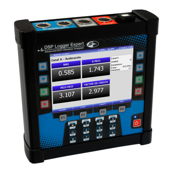
Page 43: Scalar Measurements
Offset: After selecting the measurement parameters, confirm with function key F1. Scalar measurements: When selecting a scalar measurement of any variable vibration, the screen displays the RMS, 0- peak, and peak-peak crest factor. User Manual • Version 2.0_2013 www.semapi.com... - Page 44 The function keys are enabled for different options. With the F1 key you can change the variable to measure. You can also switch between pre-set and determined variables. User Manual • Version 2.0_2013 www.semapi.com...
-
Page 45: Multivariable
1 kHz Envelope: 500 Hz Acceleration: 10 kHz Displacement: 100 Hz Multivariable: This screen shows RMS velocity measurements, RMS Envelope, RMS acceleration, and RPM acceleration. Channel change: The channel can be changed by pressing F3. User Manual • Version 2.0_2013 www.semapi.com... -
Page 46: Spectral Measurements
Once selected and configured, all the parameters for a spectral measurement can be shown in a broad spectrum on the display. In this type of measurement, markings remain active. The harmonic cursor is activated by the 1 key. User Manual • Version 2.0_2013 www.semapi.com... - Page 47 The details of the marking cursor may be in a box on the right side of the screen. Also included are 0.Pico values, Peak-Peak, and Crest Factor. Once you locate the cursor, you can start dialing the harmonics with the 3 key. User Manual • Version 2.0_2013 www.semapi.com...
- Page 48 A yellow mark on the top left of the screen indicates functions since cursor measurement stops. You can re-activate the measurement, disabling the cursor mark, with the 1 key. To record the measurement you must activate function key F1. User Manual • Version 2.0_2013 www.semapi.com...
-
Page 49: Spectrum / Waveform
Spectrum / waveform: The function is activated by pressing F2. F2 activates a waveform graphic, shown below. Pressing F2 can return to the spectrum. To record the measurement you must activate the function key F1. User Manual • Version 2.0_2013 www.semapi.com... -
Page 50: Waveform Measurements
To record the measurement you must activate the function key F1. Channel change: Use key F3 to change the channel. To exit the measurement, activate the function key User Manual • Version 2.0_2013 www.semapi.com... -
Page 51: Dual Channel Measurements And Triaxial
Channel A and Channel B of the equipment patch panel, respectively. The conventional cable connection sensor is sufficient for these measurements. After selecting the type of channel for measurement parameters, confirm by selecting F4 and NEXT. User Manual • Version 2.0_2013 www.semapi.com... - Page 52 F1. Start measurement by pressing the function key F1. The display shows the spectrums of the two inputs, the RMS values of each title, and the selected configuration parameters for that measurement. User Manual • Version 2.0_2013 www.semapi.com...
-
Page 53: Channel Change
You can access the spectrum display and simultaneous waveform of the selected channel or access the cursor and its harmonics. To return again to the measurement dual channel, select function key F3. User Manual • Version 2.0_2013 www.semapi.com... -
Page 54: Triaxial Measurements
Measurer and Analyzer User Manual Press F4 to exit the measurement. Triaxial measurements: With the DSP Logger Expert equipment, you can connect two triaxial sensors and measure the 3 signals of each simultaneously. You must set the parameters of the measurement and triaxial channel option A or B as appropriate. -
Page 55: Channel Change
The application can be changed via key F3. For triaxial measurement, changing the channel has individual measurement options for each sensor measurement axis. The measuring inputs are grouped in Channel A and Channel B. User Manual • Version 2.0_2013 www.semapi.com... -
Page 56: Instructions For Use
It is the direction radial from the transducer towards the center of the arrow and is 90 degrees tangential radial to the shaft. The sensor uses the DSP Logger Expert to identify the top measuring axes of vibration. User Manual • Version 2.0_2013... -
Page 57: Troubleshooting
SEMAPI provides technical information on the Internet, to help use their products: www.dsplogger.com , can find technical manuals, a database with frequently asked questions and application notes. You can also find instructional videos Firmware of the DSP Logger Expert in: https://www.youtube.com/user/semapicorp User Manual • Version 2.0_2013 www.semapi.com...
Need help?
Do you have a question about the DSP Logger Expert and is the answer not in the manual?
Questions and answers