Table of Contents
Advertisement
Quick Links
Advertisement
Table of Contents

Related Manuals for SEMAPI DSP Logger Expert

Summary of Contents for SEMAPI DSP Logger Expert
- Page 2 User Manual Hardware Ver.: 2.0...
-
Page 3: Table Of Contents
Hardware User Manual Hardware Technical Specifications:........3 Important User Information: ........6 Hardware DSP Logger Expert:......7 Introduction: ............7 Programs: ............8 Keyboard: ............9 Navigation keys: ..........10 Main Keyboard: ..........10 Main keyboard with direct function: ....11 Battery charge: .......... -
Page 4: Technical Specifications
Hardware User Manual DSP Logger Expert Technical Specifications: Attributes DSP Logger Expert Inputs Channels 6 (SIX) Measurements from the inputs •Acceleration, velocity, displacement from installed sensors or portable monitoring systems • AC / DC sensors • Pressure sensors • Temperature sensors •... - Page 5 1%, 5% and 10% of Fmax. Filters, ESP • 1.25-2.5 kHz • 2.5-5 kHz • 5-10 kHz Attributes DSP Logger Expert Frequency response 0,2 a 20 kHz Cutting low frequencies 0.18-100 Hz Averages Programmable from 1-4096...
- Page 6 When making installations with extensive cables, use extreme caution with all moving parts of the machine and installation of the sensors. The DSP Logger Expert can be operated in the rain and supports significant water on the connectors and keyboard. Grade: IP 65.
-
Page 7: Important User Information
Because of this difference, and also because of the great variety of uses for solid conditions equipment, all persons responsible for applying this equipment must take all appropriate electrical safety measures and study for impact damage. SEMAPI will responsible indirect consequential damages resulting from the misuse of this equipment. -
Page 8: Hardware Dsp Logger Expert
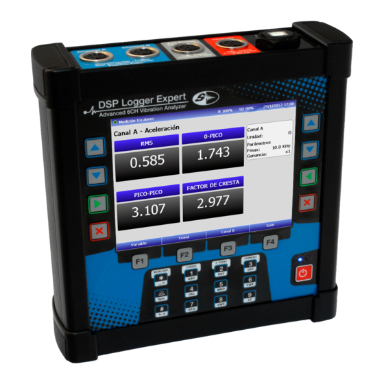
Hardware User Manual Hardware DSP Logger Expert: Introduction: The DSP Logger Expert is a vibration measurement platform with 6 channel input accelerometer signals, 4 channels of AC, and 2 channels of DC. It also has tachometer input for phase measurement and headphone output. -
Page 9: Programs
Hardware User Manual Programs: The DSP Logger Expert contains up to 6 (six) different operating programs. These programs are independent of each other and may restrict access, depending on the version acquired. Each of these programs can be updated without having to physically open the equipment and can be charged via a USB communication port. -
Page 10: Keyboard
The blue indicator will be lit when the equipment is active. The equipment keyboard has: 12 alphanumeric keys 4 navigational keys, duplicated on both sides 4 keys for functions related to screen actions. User Manual • Version 2.0_2013 www.semapi.com... -
Page 11: Navigation Keys
Main Keyboard: The alphanumeric keypad is used to enter names, equipment codes, and comments on all modules. In spectrum measurement, pressing the appropriate key can activate the cursor, maximum peas, harmonics, and zoom axis. User Manual • Version 2.0_2013 www.semapi.com... -
Page 12: Main Keyboard With Direct Function
If repeated loading is desired after completing the cycle, plug the charger in again. If the pack is sufficiently charged, the cycle will not start and the LED will remain off. User Manual • Version 2.0_2013 www.semapi.com... - Page 13 The battery condition indicator is shown in most DSP Logger Expert screens, and the positive or negative of the battery can be easily observed in stages: If after a load the indicator does not read as full, disconnect and reconnect the charger to repeat the period.
-
Page 14: Display Control
Where the ambient light is not strong or there is no sunlight, it is recommended that you lower the brightness of the screen. This will add up to 2 hours of additional battery life. User Manual • Version 2.0_2013 www.semapi.com... -
Page 15: Utilities
DSP Expert Logger. To access the utilities, press the 6 key or select the icon: Utilities. When accessed, the display will show different icons for each function. User Manual • Version 2.0_2013 www.semapi.com... -
Page 16: Pc Connection
The hardware will wait for the connection of the USB cable to a port on a PC. Important: If you connect the USB cable before activating the function, it is possible that you will not access the hardware connection to the software. User Manual • Version 2.0_2013 www.semapi.com... -
Page 17: Battery
20 seconds. The consumption changes on the equipment are associated with continuous measurement of the number of connected sensors and especially to the brightness of the display. User Manual • Version 2.0_2013 www.semapi.com... -
Page 18: Adjust Date/Hour
To change the values, use the up and down keys to move from field to field, and change numbers up and down with function keys F1 and F2. To save the set values , press function key F3. User Manual • Version 2.0_2013 www.semapi.com... -
Page 19: Display
F1 and Adjusting the brightness of the display will also change the equipment’s battery capacity, so it is recommended that you adjust this value only in the most extreme visibility conditions. User Manual • Version 2.0_2013 www.semapi.com... -
Page 20: Top Connection Panel
The connector has 7 contacts for different applications: Channel A (+) Accelerometer CH1 Auxiliary Vdc 1 (+) Accelerometer CH3 (+) Accelerometer CH5 Auxiliary Vdc 1 Vsys User Manual • Version 2.0_2013 www.semapi.com... - Page 21 This entry is dedicated to the optical sensor for phase measurement and an output for earphones. Additionally, it has other auxiliary inputs for connecting amperometric clamp, DC Aux 1, and an additional input battery charger (not specified in the panel). User Manual • Version 2.0_2013 www.semapi.com...
-
Page 22: Usb
The access the conventional USB connector, use USB Cable A / B. This can be used to upload and download data to and from a PC and to update different versions of the firmware. User Manual • Version 2.0_2013 www.semapi.com... -
Page 23: Input And Sensor Measurements
Input and sensor measurements: Accelerometers Channels 1-2-3-4-5-6 Acceleration Velocity Displacement Envelopment Speedometers Channels 1-2-3-4-5-6 Velocity Displacement Proximiters Channels AC 1-2-3-4 Displacement Amperometric Clamp Channels AC 1-2-3 Current Dual Sensors: Vibration and temperature Channels DC 1-2 Temperature User Manual • Version 2.0_2013 www.semapi.com... - Page 24 Hardware User Manual Frequency response measurement of vibration: Accelerometers Channels ICP Velocity fmax=50 Hz Velocity fmax=100 Hz Velocity fmax=1000 Hz 1000 User Manual • Version 2.0_2013 www.semapi.com...
- Page 25 Hardware User Manual Accelerometers Channels ICP Displacement fmax=50 Hz Displacement fmax=100 Hz Displacement fmax=200 Hz User Manual • Version 2.0_2013 www.semapi.com...
- Page 26 Hardware User Manual Accelerometers Channels ICP Acceleration fmax=10000 Hz 2000 4000 6000 8000 10000 Acceleration fmax=100 Hz User Manual • Version 2.0_2013 www.semapi.com...
- Page 27 T of transition of Filter 1 % (sec) T of transition of Filter 2,5 % (sec) T of transition of Filter 5 % (sec) T of transition of 0.25 0.05 Filter 10 % (sec) User Manual • Version 2.0_2013 www.semapi.com...
- Page 28 Hardware User Manual Curves for gain setting of the converter AD: User Manual • Version 2.0_2013 www.semapi.com...
-
Page 29: Accessories List
DSP-P1000B Amperometric clamp: 0-1000 A BS350 Digital Balance: 350g CB105-E3C Splitter of 3 channels for unidirectional sens. DSP-CAL-E Calibration DSP Logger Expert To order, please visit: ventas@semapi.com.ar sales@semapi.com Or the network of authorized distributors: http://www.dsplogger.com/distribuidores.php User Manual • Version 2.0_2013... -
Page 30: Troubleshooting
SEMAPI provides technical information on the Internet for help with product use: visit www.dsplogger.com for technical manuals, a database with frequently asked questions, and application notes. You can also find instructional videos about firmware for the DSP Logger Expert at: https://www.youtube.com/user/semapicorp User Manual • Version 2.0_2013... -
Page 31: Official Certificate Of Guarantee
The guarantee period begins at the local installation and verification of operation by the staff of the purchasing company. SEMAPI Corp. and SEMAPI ARGENTINA S.A. reserve the right to void this guarantee under the following conditions: • Damage caused by blows, falls, misuse, and/or other accidents.
Need help?
Do you have a question about the DSP Logger Expert and is the answer not in the manual?
Questions and answers