Advertisement
Quick Links
SEISMIC VIBRATION
Installation Guide
General information
The seismic sensor SH-V is designed to detect attempts to destroy
concrete walls and floors, brick walls, wooden structures, plywood,
compound glass, armoured glass, standard metal safes, metal cabinets
and ATMs.
The unit provides immunity against acoustic noise, accidental impacts
on monitored structures, prolonged vibration produced by transportation
facilities, lifts, ventilation systems, and water supply systems. The unit
also provides immunity to electromagnetic interferences, electrostatic
discharges and supply voltage dips.
Energized form A (NC) alarm relay.
Main features
- Versatile types of monitoring:
entire indoor surfaces or specific areas;
basic part of an object surface (fig. 3);
a full-size surface of an object (fig. 4), including adjacent structures
(fig. 5).
- Possibility to be mounted singly or in groups.
- Automatically selected algorithm of microprocessor operation according
to the impact types and instruments.
- Tamper output.
- LED indication of sensor status and protected object vibration.
- Selectable LED indication modes of alarm memory.
- Disabling of LED indication if required.
- Three test modes to ensure proper sensitivity adjustment.
Principal specifications
Alarm period
Warm-up period
Supply voltage
Current consumption
Operating temperature
Size
Weight
Mounting
Sensor mounting examples are shown of fig. 3-11, where A1 = sensor,
L = radius (range) of detection;
<=1.9 m; L1<=3/4L; L2+L3 <=2.0 m.
L
Mounting on a brick wall or on a concrete structure
To install the sensor on a brick wall, drill into the wall two holes 5 mm in
diameter and 40 mm in depth, not counting the thickness of any decorative
coating (which must not exceed 15 mm). Insert (factory-supplied) brass
anchor into the hole until the stop and fix the sensor in position by means
of (factory-supplied) screw.
Mounting on a wooden structure
To install the sensor on a wooden structure (fig. 6,8,9), drill two holes
(2,5+0,2) mm in diameter and (25+2) mm in depth in the structure to be
monitored, not counting the thickness of any decorative coating, which
must not exceed 10 mm. Then, fix the sensor by means of the (factory-
supplied) wood screws.
Mounting on a control unit of a bank automatic teller machine
(ATM), or on any metal cabinet surface
To install the sensor on a surface of an ATM control unit (to protect its
front panel against vandalism) (fig.10) or on any metal cabinet surface,
drill two holes on a lateral surface of sufficient thickness to accept at
least two M4 threads, then cut an M4 tap and thereafter fix the sensor
in position by means of M4 screws.
Mounting on a money holding unit of a bank automatic teller
machine (ATM) or on an armoured safe
To install the sensor on a surface of an ATM money holding unit (fig. 9)
or on a surface of an armoured safe (fig. 7) it is necessary to remove
decorative coatings over an area sufficient for the sensor installation. Then
the sensor must be glued to the surface by means of appropriate glue.
Mounting the sensor for monitoring of hollow glass blocks
Mounting can be carried out in either of two ways:
- Directly adjacent to the glass blocks to be monitored (fig. 11a). In this
case, the factory-supplied sensor mounting fixtures are well suited to
for installation into the cement joints between glass blocks, just as in
mounting the sensor on a brick or concrete structure.
- On a brick, concrete or metallic structure adjacent to a monitored object
(fig.11b). In this case, mounting should be carried out according to the
appropriate procedure described above.
SENSOR
«SH-V»
not less than 2 sec
not more than 10 sec
9-17 V DC
not more than 25 mA
minus 30...+50°C
105x45x35 mm
Mounting of the sensor for monitoring of shielding glasses
In this case, the sensor is mounted either on the frame of the monitored
glass, or on a brick, concrete or metallic structure adjacent to the
monitored glass, according to the appropriate procedure described above.
Wiring of the sensor
W i r i n g d i a g r a m s a r e s h o w n o n f i g. 1 and fig. 2, where A1=
sensor; G1 = power supply unit; R1, R2 = EOL resistors; Z1, Z2 = signal
loops.
A1
Tamper
+
12V
-
Alarm
A1
Tamper
+
12V
-
Alarm
Switches
Preparation of the sensor for adjustment is performed by means of
switches "1", "2" and "3" (table 1).
Switch
Test mode ON/OFF; Setting of test mode type by suc-
1
2
3
0.2 kg
Switch "1" works on a "ring principle", i.e:
- switching it ON once corresponds to setting the first type of test mode;
- switching it ON twice corresponds to setting the second type of test
mode;
- switching it ON three times corresponds to setting the third type of
test mode;
- the next switching OFF cancels the test mode.
Note: The unit automatically cancels the test mode after 6 min.
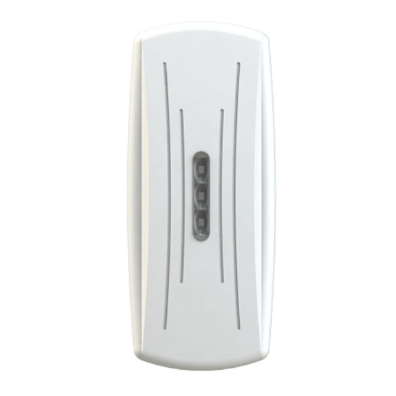
LED Indications
Three LEDs at the front of the unit are used to indicate its status.
Green LED indicates vibration; the indication is ON when the sensor detects
vibration of the monitored surface.
Red LED indicates alarm. The indication is ON in case of alarm for not less
than 2 seconds if the alarm memory is OFF. If the alarm memory is ON then
the red LED indication is ON in case of alarm, until the unit is unpowered.
The yellow LED is used only in test mode, to indicate the sensitivity level
setting. The first level: intermittent, infrequent flashing (2 flashes per sec),
the second level: intermittent, frequent flashing (10 flashes per sec) , the
third level: continuous light.
Preparation for sensor adjustment
Set switches «2» and «3» in ON position and turn the R4 control clockwise
to the stop (max sensitivity).
Apply power to the sensor. All the three LED indicators will light
momentarily, and, if everything is OK, then go dark.
A lighted Green LED indicates a relatively high level of interference due to
vibration in the monitored structure. Take action to reduce interference.
A lighted Red LED intermittently for more than 2 seconds indicates that
there is a power supply malfunction – supplied voltage is smaller than
permissible for the sensor. Correct the malfunction.
A «Norm» signal is accompanied by normal closing of relay contacts.
Set the sensor for minimum sensitivity by turning the R4 control counter-
clockwise to the stop.
Adjustment when the sensor is mounted on an armoured safe,
metal cabinet or door, on a standard safe
- Set the unit for test mode I. To do this set «1» switch to its ON position
(OFF->ON). Slow flashing of the yellow LED indicates the correct setting.
- Attach a steel plate to a safe outside surface at a place the most distant
from the sensor.
- To produce test signals, drill holes in the plate 2-3 mm in depth. Increase
the sensitivity of the sensor (by means of the R4 control) up to the level
Fig. 1. Wiring diagram
One-zone
o f t h e s e n s o r w i t h
Control
Z1
G1
combined "Alarm" and
panel
"Tamper" signals.
R1
R1
Fig. 2. Wiring diagram
o f t h e s e n s o r w i t h
Z1
Multi-zone
separated "Alarm" and
Control
"Tamper" signals.
panel
G1
R2
Z2
Designation
cessive turning the switch from OFF to ON
Alarm memory ON/OFF
LED indication ON/OFF
Advertisement

Related Manuals for Rielta SH-V


Summary of Contents for Rielta SH-V
- Page 1 Installation Guide General information Tamper The seismic sensor SH-V is designed to detect attempts to destroy Fig. 1. Wiring diagram concrete walls and floors, brick walls, wooden structures, plywood, One-zone o f t h e s e n s o r w i t h...
- Page 2 LED lights after three cycles of sawing. (In that «RIELTA» JSC, www.rielta.com case, an «Alarm» signal should be generated.) Chapaeva Str. 17, Saint Petersburg, Russia, 197101, rielta@rielta.com Adjustment when the sensor is mounted on a brick or Tel./fax: +7 (812) 233-0302, 703-1360 concrete building structure or for anti-vandal protection Technical support, tel.: +7 (812) 233-29-53, 703-13-57, support@rielta.ru...
Need help?
Do you have a question about the SH-V and is the answer not in the manual?
Questions and answers