
Subscribe to Our Youtube Channel
Related Manuals for ASCOM CR4


Summary of Contents for ASCOM CR4
- Page 1 TD 92724EN Installation Guide CR4 and CR6 Battery Pack Charger for Ascom 20 May 2015/ Ver. D...
-
Page 2: Table Of Contents
Installation Guide TD 92724EN CR4 and CR6 Battery Pack Charger for Ascom Contents 1. Introduction ........................1 1.1 Safety ........................2 1.2 Regulatory Compliance Statements (EU and EFTA only)........2 1.3 Regulatory Compliance Statements (USA and Canada only) ......... 2 2. -
Page 3: Introduction
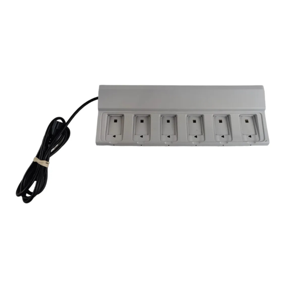
CR4 and CR6 Battery Pack Charger for Ascom 1. Introduction Introduction This document describes how to install and operate the CR4 and CR6 Battery Pack Charger. CR4 charges batteries for d62, d81, and i62 handsets. CR6 charges batteries for Ascom Myco handsets. -
Page 4: Safety
Installation Guide TD 92724EN CR4 and CR6 Battery Pack Charger for Ascom 1. Introduction Single Unit The Battery Pack Charger can be installed as a single unit. Multiple Units A number of Battery Pack Chargers and Charging Racks may be connected together. - Page 5 Installation Guide TD 92724EN CR4 and CR6 Battery Pack Charger for Ascom 1. Introduction be determined by turning the equipment off and on, the user is encouraged to try to correct the interference by one or more of the following measures: •...
-
Page 6: Installation
• Inlet accessory kit, including cable support holders and screws • Table adapters A suitable extension cord is needed to connect a single unit to a wall outlet, unless the C14 connector is replaced (by an electrician). The following item can be ordered from Ascom: Item no. Item 660339 Extension cord, 0.35 m, C13–EU... -
Page 7: Remove The Top Cover
Installation Guide TD 92724EN CR4 and CR6 Battery Pack Charger for Ascom 2. Installation disconnect the batteries or the handsets (vertical distance) and to be able to open the top cover (horizontal distance). When you are planning the location of the units, start to mount them in a height that makes it easy to reach the batteries. -
Page 8: Electrical Installation
Installation Guide TD 92724EN CR4 and CR6 Battery Pack Charger for Ascom 2. Installation Mount the two table adapters in the two outer holes in the bottom cover of the Battery Pack Charger as shown in figure 4 on page 6. -
Page 9: Install Multiple Units
Installation Guide TD 92724EN CR4 and CR6 Battery Pack Charger for Ascom 2. Installation CR with IEC C14 connector and an extension cord with an IEC C13 connector. Test Installation Connect the power cord to the wall outlet. Place a battery in the charging slot. - Page 10 Installation Guide TD 92724EN CR4 and CR6 Battery Pack Charger for Ascom 2. Installation Remove the C14 connector from the power cord. Measure, cut and strip the power cord. Connect the power cord to the disconnect device. The IEC color code is used in the power cord supplied.
- Page 11 Installation Guide TD 92724EN CR4 and CR6 Battery Pack Charger for Ascom 2. Installation Remove the C14 connector from the additional unit. Cut and strip the power cord to the length required. Run the power cord through the cable support holder of the previous unit.
- Page 12 Installation Guide TD 92724EN CR4 and CR6 Battery Pack Charger for Ascom 2. Installation Test Installation When the fixed installation is completed, apply AC power by switching on the disconnect device. Place a battery in the charging slot. A yellow LED indicates that charging starts while a green LED indicates a fully charged battery.
-
Page 13: Operation
Installation Guide TD 92724EN CR4 and CR6 Battery Pack Charger for Ascom 3. Operation Operation IMPORTANT: It is not allowed to charge an EX classified battery pack separate. Do not place the EX classified battery pack in the charging slot. -
Page 14: Troubleshooting
Installation Guide TD 92724EN CR4 and CR6 Battery Pack Charger for Ascom 4. Troubleshooting Troubleshooting Fault Solution Charging does not start Check that the battery is properly inserted in the charger. Check the AC power supply connection. 20 May 2015/ Ver. D... -
Page 15: Related Documents
Installation Guide TD 92724EN CR4 and CR6 Battery Pack Charger for Ascom 5. Related Documents Related Documents Data Sheet, CR4 Battery Pack Charger TD 92723GB Data Sheet, CR3 Charging Rack TD 92721GB Data Sheet, CR6 Battery Charging Rack TD 93054EN... -
Page 16: Document History
Installation Guide TD 92724EN CR4 and CR6 Battery Pack Charger for Ascom 6. Document History Document History For details in the latest version, see change bars in the document. Version Date Description 22 October 2010 First released version 26 September 2011 Document replaces TD 92573GB.
Need help?
Do you have a question about the CR4 and is the answer not in the manual?
Questions and answers