Columbus McKinnon DORNER DCMove Series Installation, Maintenance & Parts Manual
Hide thumbs
Also See for DORNER DCMove Series:
- Installation, maintenance, and parts manual (32 pages)

Subscribe to Our Youtube Channel
Related Manuals for Columbus McKinnon DORNER DCMove Series

Summary of Contents for Columbus McKinnon DORNER DCMove Series
- Page 1 ® DCMove Series Conveyors Installation, Maintenance & Parts Manual For other service manuals visit our website at: www.dornerconveyors.com/manuals-literature Record Conveyor Serial Number Here 851-980 Rev. A...
-
Page 2: Table Of Contents
Table of Contents Introduction ................. 4 End Drive and iDrive Conveyors ......27 Warnings − General Safety ..........5 Center Drive Conveyors.......... 29 Product Description ............. 6 End Drive and iDrive Conveyors ......31 Specifications ..............6 Center Drive Conveyors.......... 32 Models: ................ - Page 3 Table of Contents Tall Cleated Belt Return Support ........82 Table Top Mounting Brackets........83 Short Support Stands ............84 Support Stands..............85 Tall Support Stands ............86 Conveyor Belt Part Number Configuration....88 Flat Belt Part Number Configuration......88 Cleated Belt Part Number Configuration....
-
Page 4: Introduction
Introduction Dorner’s Limited Warranty applies. IMPORTANT Dorner reserves the right to make changes at any time without notice or obligation. Some illustrations may show guards removed. DO NOT operate equipment without guards. Dorner has convenient, pre−configured kits of Key Service Parts for all conveyor products. -
Page 5: Warnings − General Safety
Warnings − General Safety A DANGER A WARNING The safety alert symbol, black triangle with white exclamation, is used to alert you to potential personal injury hazards. A DANGER EXPLOSION HAZARD! • DO NOT OPERATE CONVEYORS IN AN EXPLOSIVE ENVIRONMENT. The electric gearmotor generates heat and could ignite combustible vapors. -
Page 6: Product Description
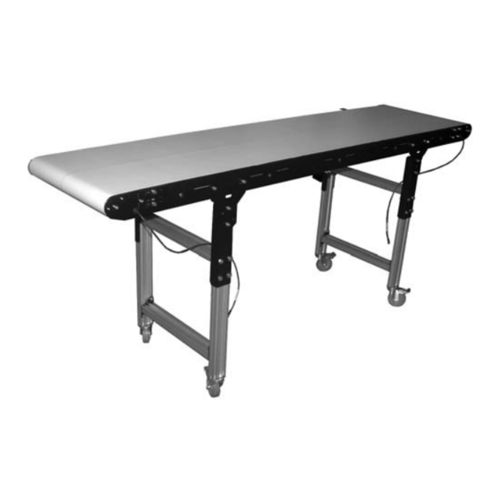
Product Description Refer to Figure 1 for typical conveyor components. Figure 1 Conveyor Gearmotor Mounting Package Gearmotor Support Stand Drive End Idler/Tension End Figure 1 Specifications Models: Flat Belt DCMove End Drive Conveyor Flat Belt DCMove iDrive Conveyor 3SE M WWWW LLLLL V D P I F T P M X... -
Page 7: Cleated Belt Dcmove Idrive Conveyor
Specifications Cleated Belt DCMove iDrive Conveyor DCMove Support Stands 3SC M WWWW LLLLL V D P I 3SZ M WWWW HHHH HHHH B S TT F B SSSS F T P M X Belt Floor Speed Interface Control Stand Type Power Type Supply... -
Page 8: Center Drive Conveyor Specifications
Specifications Center Drive Conveyor Specifications Conveyor Width Reference (WWWW) 0254, 0305, 0356, 0406, 0457, 0508, 0559, 0610, 0660, 0711, 0762, 0813, 0864, 0914, 0965, 1016, 1067, 1118, 1168, 1219 Conveyor Belt Width 254 mm (10"), 305 mm (12"), 356 mm (14"), 406 mm (16"), 457 mm (18"), 508 mm (20"), 559 mm (22"), 610 mm (24"), 660 mm (26"), 711 mm (28"), 762 mm (30"), 813 mm (32"), 864 mm (34"), 914 mm (36"), 965 mm (38"), 1016 mm (38"), 1067 mm (40"), 1118 mm (44"), 1168 mm (46"), 1219 mm (48") -
Page 9: Idrive Gearmotor Specifications
Specifications iDrive Gearmotor Specifications Speed Belt Speed In-lb (Nominal) M/min Ft/min 39.1 1-10.4 3.3-34 26.2 1.5-15.4 4.9-51 19.2 2.1-21.1 6.9-69 15.7 2.6-25.7 8.5-84 10.6 3.8-37.9 12.5-124 62.7 12.9 113.76 0.8-7.5 2.6-25 93.3 76.32 1.1-11.2 3.6-37 127.5 55.84 1.5-15.3 4.9-50 155.6 45.76 1.9-18.6 6.2-61... -
Page 10: Installation
Installation Single Piece Frame Conveyors NOTE No assembly is required. Install stands, return rollers, and Conveyor MUST be mounted straight, flat and guiding. Refer to “Stand Installation” on page 11, “Return level within confines of conveyor. Use a level Rollers” on page 13, and “Guide Installation” on page 21. (Figure 3, item 1) for setup. -
Page 11: Stand Installation
Installation Place temporary support stands (Figure 6, item 1) at Tighten conveyor belt, refer to “Conveyor Belt both ends of the conveyor. Tensioning” on page 33. Install stand and return rollers. Refer to “Stand Figure 6 Installation” on page 11 and “Return Rollers” on page 13. -
Page 12: Stand Height Adjustment
Installation Stand Height Adjustment Conveyor Angle Adjustment To adjust height, loosen two screws (Figure 9, item 1) NOTE on upper bracket (Figure 9, item 2) on both sides of stand. Please note of the two different fastener Figure 9 locations for horizontal conveyors (Figure 10) and angled conveyors (Figure 11). -
Page 13: Return Rollers
Installation Return Rollers To adjust conveyor angle, loosen center nut (Figure 12, item 1) on bracket (Figure 12, item 2) on both sides Cleated Belt Conveyors of stand. Locate return rollers. Exploded view shown in Figure 12 (Figure 14). Figure 14 Figure 12 Figure 14 Loosen three nuts (Figure 13, item 1), and adjust... -
Page 14: Flat Belt Conveyors
Installation Flat Belt Conveyors iDrive Controller Locate return rollers. Exploded view shown in (Figure A WARNING 16). Figure 16 Exposed moving parts can cause severe injury. LOCK OUT POWER before removing guards or performing maintenance. The DCMove series iDrive is available in 2 models: •... - Page 15 Installation Install tee bar (Figure 19, item 1), and secure mounting Install cover (Figure 22, item 1) with two screws bracket (Figure 20, item 1) with two screws (Figure (Figure 22, item 2). 20, item 2). Figure 22 Figure 19 Figure 19 Figure 22 Figure 20...
-
Page 16: Setup
Installation Setup Figure 24 Conveyor speed is controlled by DIP switch settings. Use the single motor chart below to determine your maximum speed. Single Motor Chart 10.0% Motor Speed Range 1 to 10.4 M/min (3.3 to 34 ft/min) 14.0% 1.5 to 15.4 M/min (4.9 to 51 ft/min) 1000 17.0% 2.1 to 21.1 M/min (6.9 to 69 ft/min) - Page 17 Installation • Direction: DIP Switch 6 (Figure 25, item 1), and switch Figure 28 settings chart (Figure 26). Figure 25 0.050 0.100 0.500 0.300 Figure 25 0.400 Figure 26 0.500 0.600 0.700 Direction of Rotation .0.800 Figure 26 1.000 • Acceleration/Deceleration: DIP Switches 7-10 (Figure 27, item 1), and switch settings chart (Figure 28).
-
Page 18: Dual Idrive Controller
Installation Dual iDrive Controller The toggle switch (Figure 29, item 1) on the side of the controller provides additional controls. A WARNING Figure 29 Motor may start immediately once power is supplied. Exposed moving parts can cause severe injury. LOCK OUT POWER before wiring to avoid accidental startup. -
Page 19: Speed Control
Installation Install tee bar (Figure 33, item 1), and secure mounting Install cover (Figure 36, item 1) with two screws bracket (Figure 34, item 1) with two screws (Figure (Figure 36, item 2). 34, item 2). Figure 36 Figure 33 Figure 36 Figure 33 Figure 34... -
Page 20: Center Drive Gearmotor Installation
Installation Center Drive Gearmotor Installation NOTE Required Tools Gearmotor may be operated in positions 1, 3 or 4 (Figure 39). • Hex key wrenches: 2 mm, 2.5 mm, 3 mm, 5 mm • Torque wrench Figure 39 Mounting A WARNING Exposed moving parts can cause severe injury. -
Page 21: Guide Installation
Installation Guide Installation Install key (Figure 41, item 1) on drive shaft (Figure 41, item 2). Install cover (Figure 41, item 3) over bearing housing (Figure 41, item 4). High Sides Figure 41 Release belt tension. (Refer to “Conveyor Belt Tensioning”... -
Page 22: Fully Adjustable
Installation Fully Adjustable Secure mounting bracket (Figure 48, item 1) onto tee bar with two screws (Figure 48, item 2). Release belt tension. (Refer to “Conveyor Belt Figure 48 Tensioning” on page 33.) Locate position of first adjustable guide mounting bracket (Figure 46, item 1), and (from inside conveyor frame) install tee bar (Figure 46, item 2) into conveyor frame slot (Figure 46, item 3). -
Page 23: Cleated
Installation Adjust height of guide mounting shaft (Figure Fully seat tee bar (Figure 52, item 1) into slot. 50, item 1) and tighten lower knob (Figure 50, item 2). Figure 52 Figure 50 Figure 52 While holding tee bar (Figure 53, item 1) in position from inside the conveyor frame, loosely install mounting bracket (Figure 53, item 2) with screws Figure 50... - Page 24 Installation With mounting bracket (Figure 54, item 1) level with NOTE conveyor, tighten screws (Figure 54, item 2). Figure 54 When installing guiding, verify that angled cut end (Figure 56, item 1) of guiding is on the infeed end (Figure 56, item 2) of conveyor belt.
-
Page 25: Tall Cleated Belt Return Support
Installation Tall Cleated Belt Return Support Continue to slide first weld nut in channel, and install second weld nut (Figure 60, item 1). Release belt tension. (Refer to “Conveyor Belt Figure 60 Tensioning” on page 33.) Loosely install two spacers (Figure 58, item 1) with screws (Figure 58, item 2) and weld nuts (Figure 58, item 3) onto cross support (Figure 58, item 4). - Page 26 Installation Install end cap guard (Figure 63, item 1) onto return 10. Repeat to install remaining cross supports onto support (Figure 63, item 2) with two roll pins (Figure conveyor frame, as needed. 11. Align end cap guard (Figure 65, item 1) on return 63, item 3).
-
Page 27: Preventive Maintenance And Adjustment
Preventive Maintenance and Adjustment Required Tools Cleaning Use mild soap and water. Do not soak the belt. Standard Tools For /05 woven polyester and /06 black anti-static belts, use a bristled brush to improve cleaning. • Hex-key wrenches: - 2.5 mm, 3 mm, 4 mm, 5 mm, 6 mm Conveyor Belt Replacement •... - Page 28 Preventive Maintenance and Adjustment Place temporary support stands (Figure 66, item 1) at Loosen the tensioner screw (Figure 68, item 1) on each both ends of the conveyor. side of conveyor to move the tension head plate assembly (Figure 68, item 2) inward and fully release Figure 66 tension on belt.
-
Page 29: Center Drive Conveyors
Preventive Maintenance and Adjustment Remove belt (Figure 71, item 1) from conveyor, one Remove mounting brackets (Figure 72, item 2) from stand at a time. Start on one end of conveyor and work one side of conveyor. down to opposite end. If equipped, remove return rollers, guiding and accessories from one side of conveyor. - Page 30 Preventive Maintenance and Adjustment Swing down idler guard assembly (Figure 76, item 1). 10. Push shaft (Figure 79, item 1) through block (Figure Remove screw (Figure 76, item 2) from both sides of 79, item 2), and slide block towards base end (Figure center drive and remove idler guard assembly (Figure 79, item 3) of tensioner.
-
Page 31: End Drive And Idrive Conveyors
Preventive Maintenance and Adjustment Belt Installation 12. Remove locking collar (Figure 81, item 1), and slide out tensioning pulley (Figure 81, item 2). End Drive and iDrive Conveyors Figure 81 A WARNING Removing stands without support will cause conveyor to tip, causing severe injury. PROVIDE SUPPORT UNDERNEATH THE CONVEYOR WHEN CHANGING THE BELT. -
Page 32: Center Drive Conveyors
Preventive Maintenance and Adjustment Install belt (Figure 86, item 1) on conveyor. Lift Ensure a temporary support stand (Figure 87, item 1) is conveyor slightly to avoid pinching belt on temporary placed at both ends of the conveyor. support stands (Figure 86, item 2). Figure 87 Figure 86 Figure 87... -
Page 33: Conveyor Belt Tensioning
Preventive Maintenance and Adjustment Install belt (Figure 89, item 1) on conveyor. Lift Install tensioning guard (Figure 91, item 1) and secure conveyor slightly to avoid pinching belt on temporary with two screws (Figure 91, item 2). Repeat on support stands (Figure 89, item 2). opposite side. -
Page 34: Center Drive Conveyors
Preventive Maintenance and Adjustment Tighten the tensioner screw (Figure 93, item 1) on each NOTE side of conveyor to move the tension head plate assembly (Figure 93, item 2) outward, or loosen to For the longest belt and bearing life, tension move head plate assembly inward. -
Page 35: Conveyor Belt Tracking
Preventive Maintenance and Adjustment Non V-Guided Belts If proper belt tension cannot be achieved before the out of tension indicator (Figure 95, item 1) begins to turn Non V-guided belt conveyors are equipped with belt tracking red, the belt must be replaced. assemblies for belt tracking adjustment. -
Page 36: Pulley Removal
Preventive Maintenance and Adjustment Pulley Removal NOTE A WARNING Support the tension tail end of conveyor before removing screws. Remove two screws (Figure 101, item 1) and tensioner assembly (Figure 102, item 1) from tension tail end of conveyor. Exposed moving parts can cause severe Figure 101 injury. - Page 37 Preventive Maintenance and Adjustment Pull tension tail end (Figure 104, item 1) outward to Remove cover plate (Figure 107, item 1) from tension release tension tail plate (Figure 105, item 1) from slot tail assembly. (Figure 105, item 2) on conveyor frame, and remove Figure 107 tension tail end (Figure 105, item 3) from conveyor.
- Page 38 Preventive Maintenance and Adjustment Figure 110 13. On opposite end, remove screw and washer (Figure 113, item 1), and remove pulley (Figure 113, item 2) from remaining tension tail plate (Figure 113, item 3). Figure 113 Figure 110 11. Remove screw (Figure 111, item 1) and washer (Figure 111, item 2) securing tension tail plate (Figure 111, item 3) onto pulley.
-
Page 39: B − Drive Tail Pulley Removal
Preventive Maintenance and Adjustment B − Drive Tail Pulley Removal Remove drive tail end from conveyor frame by further loosening two screws (Figure 117, item 1) on both A WARNING sides of conveyor. Figure 117 Drive shaft keyway may be sharp. HANDLE WITH CARE. - Page 40 Preventive Maintenance and Adjustment Remove drive tail end (Figure 119, item 1). 10. Remove cover plate (Figure 122, item 1). Figure 119 Figure 122 Figure 122 11. Remove bearing stop plate (Figure 123, item 1). Figure 119 Figure 123 With tail assembly on an open work surface, remove the two screws (Figure 120, item 1) from cover plate.
-
Page 41: C − Nose Bar Tail Pulley Removal
Preventive Maintenance and Adjustment 13. Remove shoulder screws (Figure 125, item 1) securing 15. On opposite end, remove drive spindle assembly with backing plate (Figure 125, item 2). spindle bearing (Figure 127, item 1) from recessed pocket (Figure 127, item 2) on bearing housing (Figure Figure 125 127, item 3). - Page 42 Preventive Maintenance and Adjustment Remove four screws (Figure 129, item 1) and nose bar On opposite end of conveyor, loosen four screws tail cover plate (Figure 129, item 2). Repeat on the (Figure 131, item 1), and rotate tracking cam screw opposite side of conveyor.
- Page 43 Preventive Maintenance and Adjustment Remove screw (Figure 133, item 1) and screw (Figure Remove upper and lower spindles (Figure 135, item 1) 133, item 2) that holds spacer plate (Figure from nose bar puck (Figure 135, item 2). 133, item 3) in place. Figure 135 Figure 133 Figure 133...
-
Page 44: D −Idrive Tension End Pulley Removal
Preventive Maintenance and Adjustment Remove two screws (Figure 138, item 2) and tensioner NOTE clamp plate (Figure 139, item 1) from tension end on each side of conveyor. During reassembly, make certain that Figure 139 spindles with center mark (Figure 137, item 1) are aligned with cutout (Figure 137, item 2) in crossmember bracket. - Page 45 Preventive Maintenance and Adjustment Pull each side of iDrive tension end (Figure Figure 144 141, item 1) outward to release backing plate (Figure 141, item 2) from slot (Figure 141, item 3) on conveyor frame, and remove iDrive tension end (Figure 142, item 1) from conveyor.
-
Page 46: Center Drive Pulley Removal
Preventive Maintenance and Adjustment On opposite end, remove cover plate (Figure A WARNING 147, item 1) from pulley shaft (Figure 147, item 2) and tabs (Figure 147, item 3) on crossmember. Figure 147 Exposed moving parts can cause severe injury. REMOVE BELT TENSION before removing guards or performing maintenance. - Page 47 Preventive Maintenance and Adjustment Temporarily support idler guard assembly (Figure Loosen tensioning roller set screws (Figure 151, item 1). Remove screws (Figure 151, item 2). 154, item 1). Figure 151 Figure 154 Figure 151 Figure 154 Swing down idler guard assembly (Figure 152, item 1). Push shaft (Figure 155, item 1) through block (Figure Remove screw (Figure 152, item 2) from both sides of 155, item 2), and slide block towards tensioner block...
-
Page 48: B − Idler Pulley Removal
Preventive Maintenance and Adjustment Temporarily support idler guard assembly (Figure IMPORTANT 160, item 1). Remove screws (Figure 160, item 2). Figure 160 Use caution when removing components. Tensioning pulley can be very heavy. Use an assistant to help remove tensioning pulley, as needed. -
Page 49: C − Drive Pulley Removal
Preventive Maintenance and Adjustment C − Drive Pulley Removal Slide the idler pulley assembly (Figure 163, item 1) out of the idler guide side plate on the opposite side. A WARNING Figure 163 Drive shaft keyway may be sharp. HANDLE WITH CARE. Remove two screws (Figure 166, item 1) and channel guard (Figure 166, item 2) from each side of center drive. - Page 50 Preventive Maintenance and Adjustment Remove screws (Figure 168, item 1) and remove Loosen clamp screw (Figure 170, item 1) and remove gearmotor assembly (Figure 168, item 2) (gearhead bearing collar (Figure 170, item 2). shown with motor removed for clarity, motor can Figure 170 remain attached to gearhead).
-
Page 51: Center Drive Bearing Replacement
Preventive Maintenance and Adjustment Center Drive Bearing Replacement Loosen clamp screw (Figure 173, item 1) and remove bearing collar (Figure 173, item 2). Figure 173 A WARNING Exposed moving parts can cause severe injury. LOCK OUT POWER before removing guards or performing maintenance. -
Page 52: Drive Side Bearing
Preventive Maintenance and Adjustment Drive Side Bearing Remove spacer ring (Figure 179, item 1) and key (Figure 179, item 2). Loosen clamp screw (Figure Remove two screws (Figure 176, item 1) and channel 179, item 3) and remove bearing collar (Figure guard (Figure 176, item 2) from each side of center 179, item 4). -
Page 53: Idler Side Bearing
Preventive Maintenance and Adjustment 10. Reinstall spacer ring (Figure 182, item 1) and Loosen clamp screw (Figure 185, item 1) and remove gearmotor assembly (Figure 182, item 2). Tighten bearing collar (Figure 185, item 2). screws (Figure 178, item 1) to 17 Nm (150 in lbs). Figure 185 Figure 182 Figure 185... -
Page 54: C − Nose Bar Tail Bearing Replacement
Preventive Maintenance and Adjustment iDrive Spindle Removal and NOTE Replacement During reassembly, make certain that spindle housing assembly is oriented with zerk fitting A WARNING (Figure 187, item 1) in location as shown. Figure 187 Exposed moving parts can cause severe injury. - Page 55 Preventive Maintenance and Adjustment Loosen two screws (Figure 190, item 1) on each side Remove cover plate (Figure 192, item 1) from and end of conveyor crossmember (Figure 192, item 2) and spindle (Figure 192, item 3). Figure 190 Figure 192 Figure 190 Remove two screws (Figure 190, item 2).
-
Page 56: Idrive Motor Removal And Replacement
Preventive Maintenance and Adjustment iDrive Motor Removal and 10. Remove cover plate (Figure 194, item 1) from spindle (Figure 194, item 2) and crossmember (Figure Replacement 194, item 3). Figure 194 A WARNING Exposed moving parts can cause severe injury. LOCK OUT POWER before removing guards or performing maintenance. - Page 57 Preventive Maintenance and Adjustment Loosen two screws (Figure 198, item 1) on each side Remove cover plate (Figure 200, item 1) from and end of conveyor crossmember (Figure 200, item 2) and spindle (Figure 200, item 3) on spindle assembly. Figure 198 Figure 200 Figure 198...
- Page 58 Preventive Maintenance and Adjustment 10. Remove cover plate (Figure 202, item 1) from spindle 13. Loosen two screws (Figure 205, item 1), and remove (Figure 202, item 2) and crossmember (Figure two screws (Figure 205, item 2) securing motor onto crossmember.
-
Page 59: Idrive Controller Removal And Replacement
Preventive Maintenance and Adjustment iDrive Controller Removal and Disconnect end (Figure 210, item 1) of motor wiring from threaded end (Figure 210, item 2) on controller. Replacement Figure 210 Single iDrive Controller A WARNING Motor may start immediately once power is supplied. - Page 60 Preventive Maintenance and Adjustment Remove two nuts (Figure 212, item 1) and screws (Figure 212, item 2) securing controller assembly (Figure 212, item 3) onto mounting bracket. Figure 212 Figure 212 Remove two screws (Figure 213, item 1) holding controller (Figure 213, item 2) onto bracket assembly (Figure 213, item 3).
-
Page 61: Notes
Notes DCMove® Series Conveyors 851-980 Rev. A Dorner Mfg. Corp. -
Page 62: Service Parts
Service Parts NOTE For replacement parts other than those shown in this section, contact an authorized Dorner Service Center or the factory. Key Service Parts and Kits are identified by the Performance Parts Kits logo . Dorner recommends keeping these parts on hand. End Drive Fixed Tail Assembly Item Part Number... -
Page 63: Idrive Tail Assembly
Service Parts iDrive Tail Assembly Item Part Number Description Item Part Number Description 826-984 Motor, Type 'G' 208400 Pulley, 5 mm x 15 mm 22 tooth 826-985 Motor, Type 'F' 350404 Tracking Cam 826-986 Motor, Type 'E' 351343 Backing Plate 826-987 Motor, Type 'D' 351414... -
Page 64: Dual Motor Idrive Tension Tail Assembly
Service Parts Dual Motor iDrive Tension Tail Assembly Item Part Number Description Item Part Number Description 911-223 Washer 208400 Pulley, 5 mm x 15 mm 22 tooth 920408M Shoulder Screw, 8 mm x 8 mm 351261 Clamp Plate 920512M Socket Head Screw, 351355 Gear Pinion M5-0.80 x 12 mm... -
Page 65: Single Motor Idrive Controller
Service Parts Single Motor iDrive Controller Item Part Number Description Item Part Number Description 990602M Lock Nut 208451 Controller Assembly See Specifications chart on page 8 for conveyor belt widths. Service parts can be obtained through your distributor or directly 351510 Mounting Bracket from Dorner Mfg. -
Page 66: Tension Tail Assembly
Service Parts Tension Tail Assembly Item Part Number Description 350314 Bearing Housing 351259 Filler Plate 351261 Clamp Plate 351318 Cover Plate 351355 Gear Pinion 351467 Tension Tail Plate 351427-WWWW-M Articulation Bar 351428-WWWW-M Spindle Assembly 807-4280 Washer 812-100 O-Ring 920518M Socket Head Screw, M5-0.80 x 18 mm 920618M Socket Head Screw, M6-1.00 x 18 mm 940808M... -
Page 67: Nose Bar Tail Assembly
Service Parts Nose Bar Tail Assembly 15 Nose Bar Spindle Kit Item Part Number Description Item Part Number Description 960825MFY Flanged Cap Screw, M8 x 25 mm 351261 Clamp Plate 990602M Lock Nut 351355 Gear Pinion 3SNTS-WWWW-M Nose Bar Spindle Kit 351374 Spacer Plate, Right (Includes items 9 &... -
Page 68: Center Drive Assembly
Service Parts Center Drive Assembly 49 Center Drive Kit DCMove® Series Conveyors Dorner Mfg. Corp. 851-980 Rev. A... - Page 69 Service Parts Item Part Number Description Item Part Number Description 201732 Spacer, for SEW Gearmotors 301216 Cylinder Guard Mounting Block 807-1167 Cover 301220 End Roller Mounting Plate 920850M Socket Head Screw, M8-1.25 x 50 mm 301221 Horseshoe Guard Mounting Plate 3SCD-WWWW-M Center Drive Kit (Includes items 18, 19, 301222...
-
Page 70: Center Drive Fixed Tail Assembly
Service Parts Center Drive Fixed Tail Assembly Item Part Number Description 350314 Bearing Housing 350404 Tracking Cam 351264 Backing Plate 351267 Frame Clamp Plate 351268 Cover Plate 351427-WWWW-M Articulation Bar 351428-WWWW-M Spindle Assembly 812-100 O-Ring 920518M Socket Head Screw, M5-0.80 x 18 mm 920608M Socket Head Screw, M6-1.00 x 8 mm 920820M... -
Page 71: Center Drive Fixed Nose Bar Tail Assembly
Service Parts Center Drive Fixed Nose Bar Tail Assembly 15 Nose Bar Spindle Kit Item Part Number Description Item Part Number Description 920608M Socket Head Screw, M6-1.00 x 8 mm 350404 Tracking Cam 920618M Socket Head Screw, M8-1.25 x 18 mm 351267 Frame Clamp Plate 920820M... -
Page 72: Center Drive 90° Gearmotors
Service Parts Center Drive 90° Gearmotors Center Drive SEW Gearmotors Item Part No. Part Description Item Part Number Description 32M008HH Gear Reducer, 7.5:1 NEMA 140TC 32M128WH423EN Gearmotor, 0.25 Kw (0.33 hp), 32M010HH Gear Reducer, 10:1 NEMA 140TC 230/460 Volts, 3 Phase 32M015HH Gear Reducer, 15:1 NEMA 140TC 32M044WH423EN... -
Page 73: Frame Assembly
Service Parts Frame Assembly Item Part Number Description ----- Consult Factory for Frame Part Number 351252 Spacer Plate (not used on iDrive conveyors) 351274 Frame Spacer 351300 Connecting Bracket 351387-WWWW-M Crossmember 351388-WWWW-M Tension End Crossmember 351469-WWWW-M iDrive Tension End Crossmember 900820M Carriage Bolt, M8 x 20 mm 920812M... -
Page 74: High Sides
Service Parts High Sides DCMove® Series Conveyors Dorner Mfg. Corp. 851-980 Rev. A... - Page 75 Service Parts Item Part Number Description 300150M Drop-In Tee Bar 351493-LLLLL-M-STA 25 mm (1.00") Guiding for Single Piece Guiding 351493-LLLLL-M-STB 75 mm (3.00") Guiding for Single Piece Guiding 351493-LLLLL-M-STC 150 mm (6.00") Guiding for Single Piece Guiding 351493-LLLLL-M-SFA 25 mm (1.00") Discharge End Guiding for Multi Piece Guiding 351493-LLLLL-M-SFB 75 mm (3.00") Discharge End Guiding for Multi Piece Guiding...
-
Page 76: #13 & 43 Fully Adjustable Guides
Service Parts #13 & 43 Fully Adjustable Guides Item Part Number Description Item Part Number Description FGEC-30D Lead In Cap (Infeed End Only) 206380 Base FGRC-100 Connecting Rail 206381 Base Clamp FGRR-15x20-LLLLL-M Guide Rail 206382 Insert Clamp FGRT-3x33-LLLLL-M 1.3" Guide Rail Cover (for Profile 13 206383 Guide Cup only) -
Page 77: #14 & 44 Tool-Less Fully Adjustable Guides
Service Parts #14 & 44 Tool-Less Fully Adjustable Guides Item Part Number Description Item Part Number Description FGEC-30D Lead In Cap (Infeed End Only) 206380 Base FGRC-100 Connecting Rail 206381 Base Clamp FGRR-15x20-LLLLL-M Guide Rail 206382 Insert Clamp FGRT-3x33-LLLLL-M 1.3" Guide Rail Cover (for Profile 13 206383 Guide Cup only) -
Page 78: Cleated High Side Guiding
Service Parts Cleated High Side Guiding DCMove® Series Conveyors Dorner Mfg. Corp. 851-980 Rev. A... - Page 79 Service Parts Item Part Number Description Item Part Number Description 351476-LLLLL-M-FSBD 75 mm (3.00") Infeed Fixed End 300150M Drop-In Tee Bar Cleated Guiding for Multi Piece 351404-A Single Hole Bracket Guiding, 'D' Side 351404-B Dual Hole Bracket 351476-LLLLL-M-FSCA 150 mm (6.00") Infeed Fixed End 351476-LLLLL-M-STAA 25 mm (1.00") Cleated Guiding for Cleated Guiding for Multi Piece Single Piece Guiding, 'A' Side...
-
Page 80: Flat Belt Return Roller
Service Parts Flat Belt Return Roller Item Part Number Description 240826 Return Roller Bearing 351391-WWWW-M Return Roller Guard 351392-WWWW-M Return Roller Rod 920616M Socket Head Screw, M6-1.00 x 16 mm 351384-WWWW-M Flat Belt Return Roller Assembly (Includes items 1 through 4) WWWW = Conveyor width reference in mm 0254 - 1219 See Specifications chart on page 7 for conveyor belt widths. -
Page 81: Cleated Belt Return Roller
Service Parts Cleated Belt Return Roller Item Part Number Description 240825 Return Roller Guard 802−027 Bearing 913−100 Dowel Pin 950616M Low Head Cap Screw M6-1.00 x 16 mm 351446 Cleated Belt Return Roller Assembly (Includes items 1 through 4) See Specifications chart on page 7 for conveyor belt widths. Service parts can be obtained through your distributor or directly from Dorner Mfg. -
Page 82: Tall Cleated Belt Return Support
Service Parts Tall Cleated Belt Return Support Item Part Number Description Item Part Number Description 913-997 Roll Pin 350426-LLLLL-M Return Support for 75 mm Cleats 351475-WWWW-M-A Cross Support for 75 mm Cleats 350429-LLLLL-M Return Support for 100 mm and 150 mm Cleats 351475-WWWW-M-B Cross Support for 100 mm Cleats 350428... - Page 83 Service Parts Table Top Mounting Brackets Item Part Number Description 351517 Bracket 900825MY Carriage Blot, M8-1.25 x 25 mm 990801M Hex Nut, M8-1.25 Service parts can be obtained through your distributor or directly from Dorner Mfg. Corp. (800) 397-8664 or customerservice@dorner.com DCMove®...
-
Page 84: Short Support Stands
Service Parts Short Support Stands Item Part Number Description Item Part Number Description 920620MF Flanged Socket Head Screw, 351282 Mounting Bracket M6-1.00 x 20 mm 351489 Spacer Block (for Stand Foot) 950640M Low Head Cap Screw, M6-1.00 x 40 mm 351490 Caster Bracket 990801M... -
Page 85: Support Stands
Service Parts Support Stands Item Part Number Description Item Part Number Description 930625M Flat Head Screw, M6-1.00 x 25 mm 351282 Mounting Bracket 960897M Hex Head Cap Screw, M8-1.25 x 30 mm 351379 Channel Plate 961016M Hex Head Cap Screw, 710004 Stand Foot M10-1.50 x 16 mm... -
Page 86: Tall Support Stands
Service Parts Tall Support Stands DCMove® Series Conveyors Dorner Mfg. Corp. 851-980 Rev. A... - Page 87 Service Parts Item Part Number Description 351282 Mounting Bracket 351379 Channel Plate 710003 Tube Cover 710004 Stand Foot 710006 Crossmember Plate 710221 Caster Plate 708180P Trilobe Screw, M6-1.00 x 25 mm 710210-LLLLL-M Crossmember 710211-LLLLL-M Stand Leg 807-640 Caster 900820MY Carriage Bolt, M8-1.25 x 20 mm 900825MY Carriage Bolt, M8-1.25 x 25 mm 921016M...
-
Page 88: Conveyor Belt Part Number Configuration
Service Parts Conveyor Belt Part Number Configuration Figure 214 Flat Belt Conveyor Model Number 3SEMWWWW - LLLLL V T D I PPPP - BB Cleated Belt Conveyor Model Number 3SCMWWWW - LLLLL V T I P C - SSSS MFR. DATE: MM-DD-YYYY RoHS S/N: DORNER MFG. -
Page 89: Notes
Notes DCMove® Series Conveyors 851-980 Rev. A Dorner Mfg. Corp. -
Page 90: Return Policy
Return Policy Returns must have prior written factory authorization or they will not be accepted. Items that are returned to Dorner without authorization will not be credited nor returned to the original sender. When calling for authorization, please have the following information ready for the Dorner factory representative or your local distributor: Name and address of customer.
Need help?
Do you have a question about the DORNER DCMove Series and is the answer not in the manual?
Questions and answers