Table of Contents
Advertisement
Quick Links
Advertisement
Table of Contents

Related Manuals for South Galaxy G5


Summary of Contents for South Galaxy G5
- Page 1 SOUTH G5 GNSS Positioning System User Manual - 1 -...
-
Page 2: Table Of Contents
Contents Contents ............................- 2 - Chapter Ⅰ Preface ......................... - 4 - §1.1 Introduction ......................... - 4 - §1.2 Applications .........................- 4 - §1.3 Main Features ......................- 5 - ChapterⅡ Hardware Component ....................- 6 - §2.1 Receiver components ....................- 6 - §2.2 Bottom Components ....................- 7 - §2.3 Indicators and Keypad ....................- 8 - §2.4 Touch screen ........................- 9 -... - Page 3 ChapterⅣ Accessories ......................- 51 - §4.1 Instrument Case ......................- 51 - §4.2 Charger ........................- 51 - §4.3 Cable ..........................- 52 - §4.4 UHF Antenna ......................- 52 - §4.5 Other Accessories ......................- 52 - G5 Specifications ........................- 53 - - 3 -...
-
Page 4: Chapter Ⅰ Preface
Chapter Ⅰ Preface Read this chapter, you will have a brief knowledge of SOUTH Company and G5 measurement system. §1.1 Introduction Welcome to South Surveying & Mapping Technology CO., LTD, which is China’s leading manufacturer of surveying equipment including GNSS receivers and Total Stations. To know more about SOUTH, please visit our official website https://www.southinstrument.com/... -
Page 5: Main Features
§1.3 Main Features All Constellations and More Channels With 1598 channels, G5 is capable to track signal from 5 satellite constellations , process signal of up to 16 frequencies and provide stable and reliable accuracy. More Powerful and More Durable Thanks to the 3W Farlink radio, when it works as an UHF base station G5 is able to transmit correction data farther than others, in optimal condition the working range can be 10 to 15 km.The shock-resistant frame, water-proof frame all have been enhanced, now... -
Page 6: Chapterⅱ Hardware Component
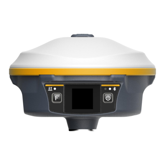
ChapterⅡ Hardware Component Reading this chapter, you can grasp the components, installation and the function of G5 positioning system §2.1 Receiver components UHF antenna port Key pad LCD touch screen - 6 -... -
Page 7: Bottom Components
§2.2 Bottom Components ○ SIM slot ○ 4 Speaker 1 Type-C port ○ 3 PPS port ○ LEMO port ○ 2 5 PIN Type-c port: USB port, OTG interface and Ethernet port.. 5-Pin port: 1. As a power port connected with an external power supply device. 2. -
Page 8: Indicators And Keypad
§2.3 Indicators and Keypad Component Description Power Button 1) Power on/off 2) Select menu 3) In lowest menu: short press for select, long press for confirmation Bluetooth Indicator Light on blue when Bluetooth connected Data Indicator Flash green when Fixed solution. Flash red when not Fixed with the correction signal. -
Page 9: Touch Screen
§2.4 Touch screen The receiver can be operated from both keypad and touch screen. By swiping the screen, receiver can be configured. 1. Swipe right /left: to shift between options (or press Fn key to shift between options) 2. Tap screen: for selection (or short press PWR key for selection) 3. - Page 10 Icons in the Coordinates display interface 1) In static mode: Coordinates and satellites Static recording Work in static mode 2) In Base mode: Datalink: WIFI Datalink status Differential correction data format 3) In Rover mode: Datalink: WIFI Datalink status Solution status - 10 -...
-
Page 11: Main Menu
§2.5.2 Main menu Main menu: by swiping screen right or press F key to bring them out. [Work mode], [Set Datalink], [System option], [Receiver information], there are two methods to bring them up: Method 1: by touch screen From main display interface, directly swipe screen right, the LCD screen will show below menus circularly as below. -
Page 12: Power Off, Reset, Set Default And Self-Check
System option [WIFI config]: to set WIFI mode. There are two WIFI mode: AP mode and Client mode. [Power saving mode]: to switch off the LCD display to save power. [Other option (USB mode, Ethernet mode, Language)]: to change language and set USB mode. -
Page 13: Set Work Mode
[Set default]: to restore to default settings. [Self-check]: to do self-check for receiver. §2.5.4 Set work mode Swipe right (or Press F key) to select [work mode], then tap screen (or press PWR key) to accept. There are three work modes:Static mode, Base mode, Rover mode (as below image): 1. - Page 14 Set [Record: open] and your required recording Interval, then swipe down to accept (or press and hold PWR key to accept) the settings. Set [Record: close] to stop recording when your field record complete. After make the settings, swipe screen down to accept (or long press PWR key (press PWR key and hold it for 3 seconds) Icon on lower right corner shows it is recording static data.
- Page 15 In coordinates display interface, you can also tap screen to enter Base mode settings. 3. Rover mode 3.1) Enter Rover mode Swipe right to select [Work mode], then select [Rover mode] ((or press F key bring out main menu and press PWR key to select [Work mode], then select [Rover mode]), the receiver will enter Rover mode.
-
Page 16: Set Datalink Mode
If you want the receiver to record static data during Rover mode, please set [Record: open] and select recording interval. Any time, you can view or change the settings of related work mode by tap the screen. §2.5.5 Set datalink mode There are 7 different type of datalink modes as below: : UHF(Inbuilt radio) as datalink : Cellular network (via SIM card) as datalink... - Page 17 Swipe right and select [Set datalink], then select [UHF(inbuilt radio)] as below. Tap the screen (or press PWR key) to make other settings for selected datalink. Air baud rate: Normally, it is recommended to take default air baud rate. If need to change it, please make the same change for both base and rover receiver.
- Page 18 4. Dual transmit datalink It means both inbuilt radio datalink and cellular network datalink:correction data is transmitted simultaneously by both inbuilt radio and cellular network via SIM card. 5. Bluetooth datalink (also called controller network datalink) Controller access to internet firstly and be connected to receiver by Bluetooth. Thus, receiver can receive correction data by utilizing controller’s network.
-
Page 19: System Option
If an external radio is connected to receiver, then external radio datalink can be chosen as datalink. 8. Close datalink Choose this option to close all datalink. Usually it is used only for test or debugging receiver. §2.5.6 System option Swipe right to select [System option] (or press F key to select), then tap it to accept (or press PWR key to accept). - Page 20 Note: suggest to close WIFI client mode if there is no need to use WIFI datalink. By default, it is set as AP mode. Power saving mode After choosing [power saving mode], the LCD display will turn dark in 2 minutes and once you tap screen or press any keypad, the screen will be activated again.
-
Page 21: Usb Mode Config
§2.5.7 WIFI config [System option]- [WIFI config] [WIFI: open/close]: to open or close WIFI function [WIFI work mode: AP/ Client] 1. AP mode The receiver will generate hotspot so that your computer or mobile phone can connected to receiver and visit its WEB UI. 2. -
Page 22: Chapterⅲ Web Ui Management
ChapterⅢ Web UI Management §3.1 Overview Because of using the smart embedded Linux operating system and SOUTH intelligent cloud technology, the web UI allows users to configure and monitor the status of G5 in real-time. The accessing way is not only by WiFi connection, but also can be USB mode. -
Page 23: Access By Usb
password. Run IE broswer on computer and input the default IP (10.1.1.1) into address bar, after a while, the system login interface is refreshed, then apply “admin” for username and password to login. IP Address: 10.1.1.1 Username: admin Password: admin §3.3 Access by USB On this mode, the USB port of G5 must work as an Ethernet port, then internal web UI shall be accessed via type-c cable connection with computer. -
Page 24: Web Ui Main Interface
Run IE broswer on computer and input the default IP (192.168.155.155) into address bar, after a “admin” while, the system login interface is refreshed, then apply for username and password to login. IP Address: 192.168.155.155 Username: admin Password: admin NOTE: The driver can be downloaded from official website automatically or please contact with us for more supports. - Page 25 In the Web UI home page, the configuration items are listed at left side. And the positioning information including coordinates information and satellites are displayed at right side. Component Description Status Positioning information, satellite tracking and the others will be displayed in this page Configuration It contains registration for receiver, base configuration, antenna...
-
Page 26: Status
Online Service Upload data onto a server in real-time User Management Add and manage the Web UI users Help Offers solutions §3.4.1 Status System Information, Work Status and Position Information are listed under Status menu. System Information In this page, all the information is diplayed such as serial number, hardware ID, MAC address, firmware version and so on. -
Page 27: Configuration
Position Information In this page, users can be clear at a glance on current position information and satellite information §3.4.2 Configuration General Config, Base Setup, Antenna Setup, Satellite Tracking, Receiver Operate and Default Language are contained under Configuration menu. Users are able to configure all kinds of parameters for G5 under Configuration menu, and all the settings are immediate effect after saving. - Page 28 General Config The registration for receiver working mode setting can be completed in this general configuration page. If the code of G5 has expired or is going to be run out, please provide the serial number of your G5 for us to apply for another available code, then input the code into the blank or register the receiver online.
- Page 29 Work Mode: There are Rover, Base and Static contained in this dropdown list Datalink: Pull down the list, there will be all kinds of options for datalink, such as radio, Network, External, Bluetooth, WIFI and CSD. Radio Route: This feature is used to transfer the correction which from the reference station to the other rover by radio, the rovers will have the same reference coordindates.
- Page 30 RadioTransfer: This is the function that G5 is able to transfer the correction from Base station to the other rovers with the internal UHF, definitely, G5 can work as a radio repeater. Note: please take in mind that the “Repeater” rover should keep away from Base station to avoid signal interference.
- Page 31 RTCM30, RTCM32. POP Value: This value is setup for the PDOP limitation. Status: Here will display the status for base in real-time. Antenna Setup The antenna parameters are configured in this page including the antenna height, measuring method. Antenna Height: This is the value for height of antenna while surveying. Measuring Method: Here provides several methods for measuring the antenna height such as carrier phase center, slant height, antenna edge, height plate and to the bottom.
- Page 32 Receiver Operate The page provides all kinds of operations to control the receiver such as self-check operation, clean epochs, factory reset, reboot and power off. Self-check: Users can also do the self-check from this configuration page, click on the Check all button to check all the modems or click on the check button corresponding to the modem to check one by one.
-
Page 33: Satellite Information
Voice Prompt: Check on this box to turn on the voice guide, uncheck it to turn off the voice guid. Voice Volume: Define the voice volume for speaker. Power: Configure the receiver to use the power saving mode or not. USB: This is used to configure G5 what kind of USB mode output from type-c port when connect the receiver with computer via USB cable. - Page 34 Skyplot In this page, all the tracking satellires are shown on the skypolt, this let users intuitively view and know where the current position of satellite is. GPS on/off For all the running GNSS constellations or the augmentation system, G5 allows to configure to use which satellite or not.
-
Page 35: Data Record
§3.4.4 Data Record The “Data Record” performance is mainly used to configure all the parameters for receiver in static mode. Much more operations can be done on G5 such as storage path, interval, data format and data files download. Recording Config The page provides more practical operations for raw data storage. -
Page 36: Data Transfer
Interval: This is the sampling interval for data storage, 20Hz sampling interval now is available for G5. File Interval: This is used to define the data storage time for the static file. Data Format: Here are 3 options to select to store what kind of format data, STH, Rinex2.0 and Rinex3.0. - Page 37 Navigation Data: This is the navigation data output from receiver such as NMEA-0183, GSV, AVR, RMC and so on. It is configured in Data Flow Config page. SIC Observation Data: This is the user-defined format observation data from SOUTH. OpenSIC Observation Data: This is the open version of SOUTH user-defined format observation data for secondary development.
- Page 38 Caster: If this working mode is selected, G5 will be a client to upload the data to a specify server if it connects to the internet by WIFI or Network connection with SIM card inserted. Input the specified IP and port for server, and the data format what is uploaded. Then users are able to see the uploaded data on server.
- Page 39 Active: Check on this circle to activate this function. Authentication Mode: This includes Eagle Mode, TCP/IP Mode and LARK Mode. Eagle Mode is SOUTH standard mode, usually, this mode is used on the case of both Base and Rover are using network mode.
-
Page 40: Network Config
§3.4.6 Network Config The “Network Config” is able to configure the ways and the contents for internet access of G5. GSM/GPRS Config, CSD Config, WIFI Config, Bluetooth Config, Port Forwarding, Router and Network Testing are under the list of Network Config. GSM/GPRS Config In this page, all the information of receiver under network mode will be displayed including the hardware information and dialing status. - Page 41 CSD Config CSD is the meaning of direct dial between Base and Rover with SIM card inserted (the CSD function should be activated on local SIM card), this function is mainly used in the area where there is very poor internet signal coverage. Status: This field displays the dialing status when CSD is used on G5.
- Page 42 Client: This option enables G5 to search and connect the other WIFI hotspot which connects to the internet, the receiver is able to download and use the mountpoint from reference station. Client_SSID: This is the WIFI hotspot which G5 is going to connect Scan: Click this button to search the surrounding available WIFI hotspot.
-
Page 43: Radio Config
Port Forwarding This page is mainly used to view and configure the internet transmission port for G5, customize and debug receiver. Router This is mainly used to view and configure the parameters for router, only under the condition of customize and debug receiver. Network Testing This function is mainly used to test network status for G5 after logging on the internet. - Page 44 Air Baud Rate: This represents the data transmission rate in the air of internal radio, the higher value, the bigger of data size transmitted per second, usually keep the default setting. Data Baud Rate: The data baud rate of SOUTH radio module has been unified to be 115200, keep it as default.
-
Page 45: Firmware Update
Update”. Firmware Update This page displays all the information of the firmware which current installed on G5, and allows to update the latest version firmware for receiver. To get latest version firmware please contact with SOUTH technician. - 45 -... - Page 46 Online Update: G5 supports to update the firmware online anytime if there is something update or optimized. Local Update: Update the latest firmware by using a firmware file. How to upgrade the firmware with Local Update Click on “Browse” button to load firmware file (Please take in mind that the firmware is ended with .img as the extension name).
- Page 47 After the firmware is completed upgrading, a dialog will appear saying “Firmware updated successfully! Host reboot, please log in later…”, then the receiver will restart automatically. Module Update This page is used to update the firmware for corresponding modem such as OEM board, radio module and sensor.
-
Page 48: Track Manage
§3.4.9 Track Manage G5 supports to record the track while doing measurement, and upload the data onto the server. Parameter Setting Data Download On this page, users can download the track data file from receiver. Choose the recording date and click “Get Data” to load all the data files recorded at that day, then choose the files and click download button. -
Page 49: Coordinate System
§3.4.10 Coordinate System G5 allows users to setup the local coordinate system on internal web UI management. The instrument would output the local coordinates according to this coordinate system. §3.4.11 Online Service This function is to upload the data onto a server real-time, including Navigation data, raw observation data, correction data, SIC observation data and open SIC observation data. -
Page 50: User Management
§3.4.12 User Management This page is used to manage the authority of login Web UI for users, including the username, password and add users. §3.4.13 System log In this page, users can record some data from G5 for fixing some bugs. - 50 -... -
Page 51: Chapterⅳ Accessories
ChapterⅣ Accessories §4.1 Instrument Case §4.2 Charger Receiver Charger Charging Cable - 51 -... -
Page 52: Cable
§4.3 Cable Type-c data cable The cable is to connect the receiver host and the computer to transfer static data and upgrade the host firmware. Type-C interface USB interface §4.4 UHF Antenna §4.5 Other Accessories Other accessories include carbon fiber pole, controller bracket, connector, tribrach, etc. The model and type of instrument accessories will change with the upgrade of the instrument. -
Page 53: G5 Specifications
G5 Specifications - 53 -...
Need help?
Do you have a question about the Galaxy G5 and is the answer not in the manual?
Questions and answers