
Subscribe to Our Youtube Channel
Related Manuals for TruTrak Digiflight II Series


Summary of Contents for TruTrak Digiflight II Series
- Page 1 Operating Handbook Digiflight II SERIES AUTOPILOTS TRUTRAK FLIGHT SYSTEMS 1500 S. Old Missouri Road Springdale, AR 72764 Ph. 479-751-0250 Fax 479-751-3397 www.TruTrakap.com...
-
Page 2: Table Of Contents
Table of Contents General Information Introduction ............... 2 Mode and Data Display ..........3 Controls ..............4 Initializing the Autopilot ........... 4 GPS Acquisition ............5 Digiflight II Lateral Modes............5 Magnetic Back-Up Mode .......... 5 Altitude Hold Mode........... 6 Minimum and Maximum Airspeed ...... -
Page 3: General Information Introduction
General Introduction The TruTrak autopilot can be defined as being an orthogonal rate system. This means that gyroscopic rate sensors are installed so as to sense motion about each of the major axes (roll, yaw, and pitch). These sensors generate the fast signal responses necessary to create an autopilot with the best possible dynamic performance. -
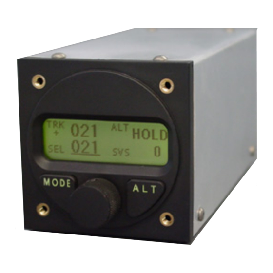
Page 4: Mode And Data Display
POWER UP—AIRCRAFT STATIONARY SEE INITIALIZING THE AUTOPILOT PAGE 4 area is used to show pitch trim. Mode and Data This display consists of three Display horizontal bars spaced This display normally vertically as the rungs on a shows operating modes and ladder, and are made to move associated numerical data. -
Page 5: Controls
Control Wheel Steering in Controls that the autopilot synchronizes The Digiflight II series to both direction and vertical autopilot uses the simplest speed upon being engaged. controls available. programming is done via a rotary encoder knob and two Initializing the... -
Page 6: Gps Acquisition
When the GPS does obtain GPS Acquisition a fix, the period will be Beneath the word HDG a replaced by an asterisk *. This • flashing period will appear means that when a certain each time the GPS sends a velocity is attained HDG will be message to the autopilot (once replaced by TRK. -
Page 7: Altitude Hold Mode
Maximum Airspeed heading source contained within the programmer and TRK The Digiflight II series is replaced with HDG. autopilots have a minimum and This maximum airspeed feature. magnetic mode is only a backup These are added only for safety. -
Page 8: Power Loss
holding the encoder knob will autopilot gyros must now be put the gyros in the fast manually re-initialized using GYRO SET centering mode. The knob operation. should depressed Manually fly the aircraft in a approximately 3 seconds during straight line as steadily as GYRO which time the words possible, while holding in the... -
Page 9: Magnetic Back-Up Mode
steering or bank commands vertical speed). To enter generated navigation altitude hold at any time, push system (EFIS or GPS). Once in and release the ALT button two GPSS times. mode, pushing the ALT button will enter the GPSV HOLD mode as well. -
Page 10: Setting Pitch Trim
If the autopilot is coupled to a autopilot is now coupled to the GPS or EFIS system which can virtual glide slope as below: provide vertical GPS steering, GPSS once mode, pushing the ALT button will GPSV ↓ GPSS enter the GPSV mode as well. To use the GPSV mode with the Setting Pitch Trim GNS 480, the aircraft must be... -
Page 11: Minimum And Maximum Airspeed
Minimum and with the aircraft stationary on Maximum Airspeed the runway and the autopilot The Digiflight II series disengaged, pressing autopilots have a minimum and holding the encoder knob will maximum airspeed feature. -
Page 12: Setup Procedure
Digiflight Setup Procedure setup consists setting activity, torque, serial LAT TORQUE baud rate, bank angle setting, micro activity, minimum PREV EXIT NEXT airspeed, maximum airspeed static lag, and magnetometer In a manner similar to calibration. To enter the lateral activity, use the encoder knob to setup mode, press and hold the select the desired value of roll MODE... - Page 13 recognize NMEA-0183 protocol advance to the next setup or Apollo GX50/GX60 protocol screen. The unit will now show (moving map output). the next screen: Once the desired baud rate GPS GAIN or Garmin protocol has been selected, again press and release PREV EXIT NEXT...
- Page 14 moved within the panel, or if to North using GPS as a new equipment is installed reference. Once this is done, the nearby. In order to skip this screen will now show: step, press and quickly release CALIBRATING the knob while is selected.
- Page 15 This concludes the lateral be between 7 and 12. A default setup procedure. value is set at the factory but To configure the pitch may need to be modified to suit portion of the autopilot push a particular aircraft. The value and hold the ALT button for 3 chosen should be sufficient to seconds.
- Page 16 The next screen in the setup This setting in most cases procedure is the static lag setup will not need to be changed. If screen. This setting should only the half step setting is set to Y be changed if autopilot tends to (yes), then the pitch servo will oscillate in pitch during altitude now have higher resolution, and...
- Page 17 TruTrak Flight Systems, Inc. (5-06) Printed in U.S.A.
Need help?
Do you have a question about the Digiflight II Series and is the answer not in the manual?
Questions and answers