Table of Contents
Advertisement
Quick Links
Polyhex Technology Co., Ltd.
DEBIX User Manual
Version: V2.5 (2023-03)
Editor: Polyhex Technology Company Limited (http://www.polyhex.net/)
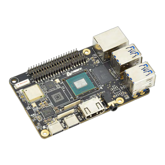
In recent years, with the ever-increasing product demand in fields of application such as
smart home, smart security, video surveillance and industrial automation, AI chips capable of
resolving problems in these fields have also emerged. Polyhex Technology has responded to
this demand with the launch of DEBIX, a development board based on NXP NPU processor
i.MX 8M Plus. It focuses on machine learning, vision processing, and industrial IoTs, meeting
the application needs of commercial and industrial fields such as education, security
monitoring, industrial automation, smart homes and smart cities.
Figure 1
1
108
/
www.debix.io
Advertisement
Table of Contents

Related Manuals for DEBIX Model A

Summary of Contents for DEBIX Model A
- Page 1 Polyhex Technology has responded to this demand with the launch of DEBIX, a development board based on NXP NPU processor i.MX 8M Plus. It focuses on machine learning, vision processing, and industrial IoTs, meeting the application needs of commercial and industrial fields such as education, security monitoring, industrial automation, smart homes and smart cities.
-
Page 2: Table Of Contents
Wi-Fi Connection ....................... 30 Change Language ......................31 Setting up Access Point .....................33 Shut Down ......................... 34 The three screens supported by DEBIX ................35 Use lidar module on DEBIX ....................44 Chapter 4 Introduction of Hardware Programming ..............48 GPIO Introduction ......................48 Usage of GPIO ........................ - Page 3 Connection with DEBIX Model A ..................86 Verify Functions of LoRa Board ..................89 Chapter 7 DEBIX 4G Expansion Board ................... 91 Brief Introduction of DEBIX 4G Expansion Board ............91 Interface definition ......................91 Connection with DEBIX Model A ..................92 First use of 4G network .....................
-
Page 4: Chapter 1 About Debix
Polyhex Technology Co., Ltd. Chapter 1 About DEBIX DEBIX is essentially a versatile single board computer, which can be widely used in artificial intelligence, machine learning, industry 4.0, edge computation, gateway, IoT, security monitoring etc.. The following are some of the powerful features of DEBIX: ●... -
Page 5: Debix Structure Overview
Polyhex Technology Co., Ltd. DEBIX’s TSN technology makes it essential for Industrial 4.0 applications, as it meets the needs of industrial enterprises with precision oriented production time control, thus increasing the interconnection speed of the IoT. DEBIX Structure Overview DEBIX's interface features a compact arrangement, the interface components are visible at a glance. - Page 6 Polyhex Technology Co., Ltd. DEBIX uses NXP i.MX 8M Plus based SoC, it has 2GB/4GB/6GB/8GB memory, supports Gigabit Ethernet, dual-band wireless network and Bluetooth 5.0. The data specifications are as below: System NXP i.MX 8M Plus (default), 4 x Cortex-A53, comes with an integrated neural processing unit (NPU) that delivers up to 2.3 TOPS.
-
Page 7: Debix Tech Specs
˚ C to 105 ˚ C DEBIX Tech Specs Figure 4 Like any standard computer, DEBIX consists of a range of different computer components. The most important component is the "brain" of the computer, the system-on-chip/SoC in the center at the front of the motherboard. -
Page 8: Debix I/O Interfaces
DEBIX has 4 USB3.0 Host A ports, they are all USB3.0 interfaces. The Ethernet port is on the right side of the USB 3.0, it connects DEBIX to the network through a cable with an RJ45 connector. There are two status indicators below the Ethernet port to show the signal upstream or downstream status, one is Link, the other is Active: www.debix.io... - Page 9 TV or projector. On the left side, there is a multifunctional OTG port for programming, system updating, or USB drive & hard disk connecting etc. Next to the OTG interface is the USB Type-C power port for DEBIX power supply. We recommend using a 5V/3A power adapter to ensure sufficient power supply.
- Page 10 U77410n0der the GPIO pins, there are two connectors, the right side connector J6 is 2x6Pin LAN pins for connecting to the local network, the left side connector J10 is 2x15Pin LVDS pins, it is a LVDS display output interface, it support single channel and dual channel LVDS display. Figure 12 www.debix.io...
- Page 11 PCIe to USB. PCIe connector is FH26W-19S-0.3SHW(97). please refer to FH26W-19S-0.3SHW(97) on website https://www.debix.io/. The corresponding wire material shall meet the above connector interface requirements. Figure 13 PCIe interface pins are defined as follows:...
-
Page 12: Display Interface
2 1080p60 + HDMI 4kp30. HDMI Interface DEBIX Model A has an HDMI connector (J9) at the lower right. The connector is a type A HDMI mother base, which is used to connect the display, TV or projector. Figure 14... -
Page 13: Lvds Interface
The LVDS display bridge (LDB) connects the LCDIF inside the CPU with the external LVDS display device. The purpose of the LVDS display bridge (LDB) is to transmit synchronous RGB data to an external display device through the LVDS interface. The LVDS interface is used for the following: www.debix.io... - Page 14 (odd pixel/even pixel). It supports pixels higher than 1366x768p60 and up to 1080p60. The left tag J10 connector of GPIO connector of DEBIX Model A is 2x15Pin, which is an LVDS display output interface and supports single or dual LVDS display.
- Page 15 LVDS1 Differential data channel 1(+) LVDS1_TX2_N LVDS1 Differential data channel 2(-) LVDS1_TX2_P LVDS1 Differential data channel 2(+) To Ground To Ground LVDS1_CLK_N LVDS1 Clock differential signal path(-) LVDS1_CLK_P LVDS1 Clock differential signal path(+) LVDS1_TX3_N LVDS1 Differential data channel 3(-) www.debix.io...
-
Page 16: Dsi Interface
clock (video clock) and output clock (D-PHY HS clock) The MIPI-DSI interface (J13) of DEBIX Model A can be used to connect the MIPI display touch screen, as follows: the connector is 2 * 10Pin/1.25mm pin base. Figure 18... - Page 17 DSI Differential Clock Channels(-) DSI_CKP DSI Differential Clock Channels(+) Ground terminal DSI_DN2 DSI Differential data channel 2(-) DSI_DP2 DSI Differential data channel 2(+) Ground terminal DSI_DN3 DSI Differential data channel 3(-) DSI_DP3 DSI Differential data channel 3(+) Ground terminal Ground terminal www.debix.io...
-
Page 18: Chapter 2 Debix Installation Guide
Polyhex Technology Co., Ltd. Chapter 2 DEBIX Installation Guide DEBIX is designed to maximize the ease of use and convenience for users, as much as possible, while making sure it still works normally like a standard computer. You will need to prepare the following peripherals to make it work: Power adapter - DC5V power adapter, at least 3A rated current, equipped with USB Type-C Output. - Page 19 Users can choose to replace HDMI with the LVDS interface or MIPI DSI interface when connecting to a LVDS screen or a MIPI display. Figure 23 Note: We recommend installing a chassis/case for DEBIX before assembling the hardware, which can effectively avoid the short circuit of the motherboard components caused by accidental touch.
-
Page 20: Hardware Installation
Insert Micro SD card Prepare the Micro SD card with the operating system installed, and insert it into the card slot on the back of DEBIX. If you need to remove it, just pull out the card gently after the power is off. -
Page 21: Connect The Keyboard And Mouse
Polyhex Technology Co., Ltd. Connect the keyboard and mouse Figure 26 Connect the network cable Figure 27 Connect the power adapter Figure 28 Plug in the power to boot up, when DEBIX begins to boot, the indicator light(red) on the www.debix.io... -
Page 22: Software Installation
Software Installation Boot from the Micro SD card After downloading the latest system image file we provided to DEBIX, you can use the tool called Etcher to write the system image to the Micro SD card. Etcher supports Windows system, you also can find the corresponding version for Linux system and macOS. We have simplified the DEBIX software installation process with only the following three steps: Download link:https://www.balena.io/etcher/... -
Page 23: Boot From Emmc
Polyhex Technology Co., Ltd. Figure 30 Insert the Micro SD card into DEBIX, connect the display device and power on, then you can see the boot screen. Boot from eMMC Prepare a Micro SD card above 16GB, enter the official website of DEBIX https://debix.io/Software/download.html, find the image corresponding to the memory... - Page 24 Micro SD card, and then turn on the power. Figure 32 5. After booting, the system will automatically write to the eMMC through the Micro SD card the red indicator light on the This burn process will not be displayed on screen. When burning, www.debix.io...
- Page 25 1) Connect the motherboard to the keyboard, mouse and HDMI display, turn the DIP switch to "11" to start the system from the Micro SD card, enter the default username “debix” and password "debix" to enter the command line, and run the following commands in sequence:...
- Page 26 Polyhex Technology Co., Ltd. 2)Repeat step 5 to reprogram the eMMC. www.debix.io...
-
Page 27: Chapter 3 Using Debix
During the first boot, you will first enter the login interface. At this time, enter the default username “debix” and password "debix" to enter the desktop. Desktop Introduction The default DEBIX system we provide is with Desktop. Here is a brief exhibition. Figure 34 [A]Wallpaper... -
Page 28: System Browser
Chrome, you will be familiar with it. Figure 35 File Management Like other systems, DEBIX uses file manager as the desktop file management tool. Figure 36 The files downloaded through browser are stored in the Downloads directory under the user's... -
Page 29: First Time Use
Click “Activities” in the upper left corner to open application interface. There are some pre- installed applications. Figure 37 Open Setting, you will see some personal settings about the system, you can set up Wi-Fi, Bluetooth and other settings here: www.debix.io... -
Page 30: Change User Password
“password” to set a new user id and password: Figure 39 Wi-Fi Connection Click the Wi-Fi tab, open the switch in the upper right corner of the window, then select your Wi-Fi and enter the password to connect to the network. www.debix.io... -
Page 31: Change Language
Polyhex Technology Co., Ltd. Figure 40 Change Language If you want to change the language, select “Language and Region”, then open “Manage Installed Languages”: Figure 41 Then click ”Install/Remove Languages“ in the newly appeared window: www.debix.io... - Page 32 Figure 43 After the installation, click “Apply System-Wide”, then go back to the Language and Region tab, click “Language” at the top, select the language you want, and then click “restart”: www.debix.io...
-
Page 33: Setting Up Access Point
Figure 44 Setting up Access Point Click the application “Debix Wifi AP” application on the desktop of DEBIX, input sudo password, Access Point name, Access Point password, choose the port number(ens33 or ens34) and finally click “Create AP”, the Access Point can be created. -
Page 34: Shut Down
The power tab will show up when users click the Power Button in the upper right corner of the system. You can choose to log off, restart or Power Off to shut down. Wait until the display turns black and the status indicator (red) on the motherboard is completely off, then disconnect the power supply. www.debix.io... -
Page 35: The Three Screens Supported By Debix
C080IY28026- D60V.C(800x1280)_Product+Spec.pdf HC050IG40029-D58V.C(LVDS) 800x480 5 https://debix.io/Uploads/Temp/file/20220921/H inches LVDS screen C050IG40029- D58V.C(LVDS)%20800x480_Product%20Spec _220915.pdf HC101IK25050-D59V.C(LVDS) 1024x600 https://debix.io/Uploads/Temp/file/20220921/H 10.1 inches LVDS screen C101IK25050- D59V.C(LVDS)%201024x600_Product%20Spe c_220915.pdf HC080IY28026-D60V.C(800x1280) 8 inches MIPI screen connection method: Prepare DEBIX, FPC flat cable and the MIPI screen www.debix.io... - Page 36 Polyhex Technology Co., Ltd. Figure 48 Use same-direction 24Pin FPC flat cable to connect to J13 of DEBIX, just like the figure below: Figure 49 Figure 50 www.debix.io...
- Page 37 Polyhex Technology Co., Ltd. Figure 51 Figure 52 HC050IG40029-D58V.C(LVDS) 800x480 5 inches LVDS screen connection: Prepare DEBIX, LVDS screen cable, LVDS screen www.debix.io...
- Page 38 Pin1/2, as for the sole 2Pin blue and white line, The blue line is LVDS VCC Power EN (Active High) connected to J2 Pin36; The white line is Backlight Power EN (Active High) and PWM connected to J2 Pin38 www.debix.io...
- Page 39 Polyhex Technology Co., Ltd. Figure 54 Figure 55 www.debix.io...
- Page 40 Polyhex Technology Co., Ltd. Figure 56 www.debix.io...
- Page 41 Prepare DEBIX, LVDS screen cable, LVDS screen Figure 58 Connect the double-row female header connector to J10 of DEBIX, connect the red line to Pin1/2, as for the sole 2Pin blue and white line, connect the blue line to Pin36 of J2, connect the white line to Pin38 of J2.
- Page 42 Polyhex Technology Co., Ltd. Figure 59 Figure 60 www.debix.io...
- Page 43 Polyhex Technology Co., Ltd. Figure 61 Figure 62 www.debix.io...
-
Page 44: Use Lidar Module On Debix
Polyhex Technology Co., Ltd. Use lidar module on DEBIX Prepare the lidar module, control board of the lidar module, standard micro USB data cable and DEBIX Figure 63 For the specification of the lidar module, refer to : https://debix.io/Uploads/Temp/file/202 ... - Page 45 Polyhex Technology Co., Ltd. Use a micro USB data cable to connect the lidar module with DEBIX: Figure 66 Figure 67 www.debix.io...
- Page 46 Polyhex Technology Co., Ltd. Figure 68 Figure 69 Once finished connecting the lidar module with DEBIX, connect DEBIX with the peripherals www.debix.io...
- Page 47 Polyhex Technology Co., Ltd. (keyboard, mouse, display), insert the Micro SD card that has DEBIX system. Power on DEBIX, open the terminal, run the following command: ldlidar_stl /dev/ttyUSB0 When the lidar module begins to work, the above command will output data continuously, if you cover the lidar module, some data will change to 0 www.debix.io...
-
Page 48: Chapter 4 Introduction Of Hardware Programming
GPIO Introduction The GPIO connector is on the top edge of the DEBIX presented in the form of 2x20Pin with 2.0mm pitch. The GPIO connectors can be used to make the LED to turn on/off or blink. The GPIO pins have different applications including physical computing, power supply. - Page 49 I2C6_SCL ECSPI2_MISO I2C6_SDA ECSPI2_SCLK GPIO1_IO11 GPIO1_IO12 CAN1_TXD GPIO1_IO13 CAN1_RXD GPIO5_IO03 CAN2_TXD GPIO5_IO04 CAN2_RXD GPIO3_IO21 As for the mapped functional definition of the 40 pins of J2, please refer to DEBIX Model A Reduced GPIO Function List on website https://www.debix.io/. www.debix.io...
-
Page 50: Usage Of Gpio
DEBIX OS has built-in GPIO interface operation command, you can set GPIO by GPIO command. Important: The GPIO voltage input of Debix Mode A/B only supports 3.3V. If the input is higher than 3.3V, it may cause damage to the GPIO interface and CPU. - Page 51 Polyhex Technology Co., Ltd. Example: Set GPIO5_IO03 to output high, type command debix-gpio GPIO5_IO03 out 1, GPIO5_IO03 will output 3.3V. Example: Set GPIO5_IO03 to input rising edge, type command debix-gpio GPIO5_IO03 in 1, if Pin34 (GPIO5_IO03) detects power, the message INFO: pin:131 value=1; if the...
- Page 52 Polyhex Technology Co., Ltd. power is disconnected, the message INFO: pin:131 value=0. www.debix.io...
- Page 53 Chapter 5 DEBIX I/O Board Brief Introduction of DEBIX I/O Board DEBIX I/O board is compatible with Raspberry Pi’s camera and display, e.g. DSI display(The DSI interface can be used for Raspberry Pi’s official 7’’ display)and CSI camera. Additionally, it expands I/O interfaces of DEBIX, for example, RJ45 gigabyte LAN,RS232,RS485,CAN etc., making it more convenient communicating with industrial devices.
- Page 54 2 x 2bit DIP Switch (used for selecting USB-Debug, RS232, RS485 and CAN) Expansion 40-Pin Double-Row 3xUART, 2xI2C, 2xSPI, 2xCAN, 6xGPIO by default, refer to DEBIX Headers Model A Reduced GPIO Function List on website https://www.debix.io, they can be configure to I2S, PWM, SPDIF, GPIO etc.
- Page 55 UART2-TXD GPIO3_IO21 CAN2_TXD As for the mapped functional definition of J2 40 pins on DEBIX I/O board, please refer to DEBIX Model A Reduced GPIO Function List on website https://www.debix.io/. Connection with DEBIX Model A There is a group of I/O on the reverse side of I/O board, they are circled out with red line as...
- Page 56 Polyhex Technology Co., Ltd. There is a group of pins on the edge of DEBIX, they are circled out with red line as below: Figure 73 Align highlighted I/O of the I/O board with DEBIX pins and press them, using the approach of hole-to-pin.
- Page 57 LAN interface on each board separately, connect 1 and 2 with a colorful dupont line, there is no color sequence, just make sure that the line is inserted into the right pin. Figure 76 After connection, the boards should look like this www.debix.io...
- Page 58 Polyhex Technology Co., Ltd. Figure 77 DSI connection locations are as below Figure 78 www.debix.io...
- Page 59 Figure 79 Figure 80 After connection, the boards should look like the above figure. Connect DEBIX with peripheral devices according to Chapter 2, then the boards can work. Note: When connecting DSI and CSI interfaces, you should take care of the plugging...
- Page 60 The stations of the black rubber button are highlighted in the following figures. Figure 81 Rubber Button being pushed down Figure 82 Rubber Button being pulled up www.debix.io...
- Page 61 The DIP switch location is circled with red line in the following figure: Figure 83 Figure 84 WARNINGS: To protect the DIP switch, the following instructions should be taken care of: 1. The yellow gummed paper should be taken off 2. Do not use sharp materials to toggle DIP switch www.debix.io...
- Page 62 . DIP switches make it realizable that Figure 84 Debix is able to be compatible with Raspberry 40 pins. If you are going to use RS232,RS485,DEBUG,CAN, just turn off the corresponding switch (by default, the switches are located on the upper side, i.e., they are in the station of ON).
- Page 63 The connection between the CAN1 receiver and CAN2 receiver is described as below(the connection line is dupont line): CAN1 receiver pins CAN2 receiver pins CANH CANH CANL CANL Once connected with the corresponding peripherals, the image should look like this: www.debix.io...
- Page 64 500000 ifconfig can1 up Run the following commands to verify the communication between CAN1 and CAN2 Receive: candump can1 Send: cansend can0 123#1122334455667788 Receive: candump can0 Send: cansend can1 123#1122334455667788 CAN/RS485/RS232 www.debix.io...
- Page 65 Inverting Receiver Input Inverting Driver Output R232 UART3-RXD /dev/ttymxc2 Debix serial port receive UART3-TXD Debix serial port send The green connector in is standard industrial communication connector, its model is Figure 88 KF2EDGR-2P5_7P. As for its specification, please refer to DEBIX_I/O_board_RS232/RS485/CAN_connector_specification on website https://debix.io,...
- Page 66 RS232_TXD3 CAN sample: 1. Prepare two pieces of DEBIX + DEBIX I/O board, turn the DIP SW2-2 OFF. Note, When SW2-2 is OFF, CAN1 signals are at Pin1 and Pin2 of the green connector J12;when SW2-2 is ON(default state), CAN1 signals are at Pin11 and Pin13 of 2x20Pin J2, at this time, Pin11 and Pin13 can also be configured as other functions.
- Page 67 Receive: candump can0 Send: cansend can0 123#1122334455667788 RS485 communication sample 1. Prepare two DEBIX + DEBIX I/O board, turn the DIP SW1-2 of the two DEBIX I/O board OFF. 2. Connection between the two I/O boards(the connection line is dupont line):...
- Page 68 RS232 Sample 1. Prepare two DEBIX + DEBIX I/O board, turn the DIP SW1-1 of the two DEBIX I/O board OFF. 2. Connection between the two I/O boards are as below(the connection line is dupont line):...
- Page 69 Usage of Type-C Debug Connect DEBIX I/O board with DEBIX, connect DEBIX I/O board Debug interface and Windows computer with a type-C cable, power up DEBIX through inserting the type-C power cable. After connection, the boards should look like this...
- Page 70 Click open and then run then install,once installation is finished there will be a prompt to notify you that the driver is installed successfully. ● Right click my computer, select management, select device manager, unfold port (COM and LPT),you will see USB-SERIAL CH340, just like the figure below www.debix.io...
- Page 71 Download putty from the internet(e.g. https://www.onlinedown.net/soft/2186.htm), install it following the installation wizard. ● Open putty, select Session, select serial, input speed with value 115200, set the serial line to the serial line that shown in step 3 , finally, click open. Figure 95 www.debix.io...
- Page 72 Polyhex Technology Co., Ltd. Figure 95 Once the serial port is open, you can see the following image, you can check kernel log, alternatively, you can type linux commands. Figure 96 www.debix.io...
- Page 73 Usage of CSI Camera Prepare a camera just like the figure below Figure 97 The CSI interface on DEBIX I/O board is as below Figure 98 Connect the camera to the DEBIX I/O board, once connected, the board is as below www.debix.io...
- Page 74 Polyhex Technology Co., Ltd. Figure 99 Insert Micro SD card to DEBIX and connect DEBIX with peripheral devices (keyboard, mouse, display device..) referring to Chapter 2. Finally, the board is as below Figure 100 www.debix.io...
- Page 75 0010 (1) 15.574949] mx8-img-md: created link [imx219 1-0010] => [mxc- mipi-csi2.0] V4L2 node : /dev/video2(when there are two cameras connected to DEBIX, it’s needed to check which video node is correct.) Usage of DSI Display The DSI display interface on DEBIX I/O board is as below...
- Page 76 Polyhex Technology Co., Ltd. Figure 101 Prepare mother-to-mother dupont thread and assistant display DSI line Figure 102 Mother-to-mother Dupont Thread www.debix.io...
- Page 77 Connect the display with the I/O board using mother-to-mother dupont thread (pin2 of I/O board to 5V power pin of the display), and also, connect the assistant display DSI line. Once these two lines are connected, the display can work. Figure 104 www.debix.io...
- Page 78 Polyhex Technology Co., Ltd. Figure 105 Usage of RTC Connect DEBIX I/O board and DEBIX as the steps described above, power up DEBIX, the boards should look like this www.debix.io...
- Page 79 Open terminal, Run command dmesg | grep rtc-hym8563, the output should look like this 2.329714] rtc-hym8563 3-0051: registered as rtc1 ● Set and read RTC time Open terminal, Run command sudo hwclock --systohc ,and then run command sudo hwclock --show,the output should look like this 2022-04-01 15:17:18.348167+00:00 www.debix.io...
- Page 80 Polyhex Technology Co., Ltd. Usage of LAN2 Connect DEBIX I/O board and DEBIX as the steps described above, power up DEBIX, the boards should look like this (make sure that the LAN interface of I/O board is inserted with network cable)
- Page 81 Chapter5. Figure 108 2. Connect Raspberry Pi POE HAT and DEBIX I/O add-on board. It can be seen from the following figures that Raspberry Pi has 40-pin and 4-pin slots, connect the 40-pin slot and 4- pin slot with the corresponding parts of DEBIX I/O board.
- Page 82 Polyhex Technology Co., Ltd. Figure 109 Figure 110 3. Connect the switch(supporting POE) with DEBIX Model A www.debix.io...
- Page 83 Figure 111 Figure 112 Insert the Micro SD card into the SD card slot of DEBIX Model A, power up the switch, the red indicator of DEBIX Model A will light, which indicates that POE function is normal. It is without error that the POE HAT fan does not work, since it is not used.
- Page 84 Polyhex Technology Co., Ltd. Figure 113 Finally, you can connect DEBIX Model A with peripherals (keyboard, mouse, display), refer to chapter 2 of this document for connection steps. www.debix.io...
- Page 85 Polyhex Technology Co., Ltd. Chapter 6 DEBIX LoRa Board Brief Introduction of DEBIX LoRa Board DEBIX Model A LoRa Board is compatible with DEBIX Model A and provides a Mini PCIe interface for LoRa Module. LoRa enables long-range transmissions with low power consumption.
- Page 86 1 x LoRa Antenna Connector, 1 x Wifi Antenna Connector EEPROM 1 x 2Kbit EEPROM Clipper Chip 1 x Secure Element, e.g.ATECC608 Connection with DEBIX Model A Insert LoRa module to DEBIX LoRa board, once installed, the board is as below Figure 115 Prepare two antennas www.debix.io...
- Page 87 Polyhex Technology Co., Ltd. Figure 116 The corresponding antenna interfaces are circled out with red line as below Figure 117 Install the antennas to LoRa board, once installed, the board is as below Figure 118 www.debix.io...
- Page 88 Polyhex Technology Co., Ltd. Connect LoRa board with DEBIX, there is a group of I/O on LoRa board, there is a group of pins on DEBIX, insert the pins to corresponding I/O, press them to fix the two boards together.
- Page 89 Figure 121 Verify Functions of LoRa Board DEBIX offers compatibility with LoRa boards by default. Connect DEBIX with LoRa board following the previously described steps. and connect DEBIX with peripherals (keyboard, display, mouse, power supply) which has been described in chapter 2 .
- Page 90 Loading ARB fw INFO: [main] concentrator started, packet can now be received INFO: concentrator EUI: 0x0016c001ff1a8f79 As shown in the image above, there is a notification “success connecting the concentrator” which indicates that the LoRa module has been successfully connected. www.debix.io...
- Page 91 Chapter 7 DEBIX 4G Expansion Board Brief Introduction of DEBIX 4G Expansion Board DEBIX Model A 4G Board is an adapter board specially designed for DEBIX Model A, and the 4G Board can supplement DEBIX Model A with 4G network functions. It has a compact appearance, measuring only 57mm x 51.3mm, with a Mini PCIe 4G module slot and a Micro...
- Page 92 1 x Clamshell FPC socket, 19Pin 0.3mm Pitch 1 x 4G Operation Indicator Connection with DEBIX Model A First, paste the square shape and the round shape Mylar sheet on the front and back of the DEBIX board, as shown in the figure below: www.debix.io...
- Page 93 Figure 124 Square shape Mylar sheet Figure 125 Round shape Mylar sheet Connect the expansion board to the FPC flat cable, then install the 4G module to the DEBIX 4G expansion board (lock screw CM2.0X4), and insert the Micro SIM card (note the direction, the specific direction is shown in Figure 128).
- Page 94 Figure 129, and there is a group of pins on the edge of DEBIX, they are circled out with red line in Figure 130. Press and install the pins and the corresponding sockets, and fix them with locking screws (PM1.4X4), and connect the FPC flat cable (note the direction of the gold finger is shown in Figure 126), and the external antenna.
- Page 95 Polyhex Technology Co., Ltd. Figure 129 Figure 130 www.debix.io...
- Page 96 Polyhex Technology Co., Ltd. Figure 131 First use of 4G network Follow the steps below in order: Step 1: click ‘Add on Board’ to select the "Debix + 4g board". www.debix.io...
- Page 97 Polyhex Technology Co., Ltd. Figure 132 Step 2: select "None", and click "OK". www.debix.io...
- Page 98 Polyhex Technology Co., Ltd. Figure 133 Step 3: click "Start", and then click "OK". www.debix.io...
- Page 99 Polyhex Technology Co., Ltd. Figure 134 Restart the device to take effect. Step 4: dial-up Internet access steps: Enter the settings, select Network, enable Mobile Broadband, and select "Add new connection". www.debix.io...
- Page 100 Polyhex Technology Co., Ltd. Figure 135 www.debix.io...
- Page 101 Polyhex Technology Co., Ltd. Step5: select the country according to the actual location, taking "China" as an example: Figure 136 Figure 137 www.debix.io...
- Page 102 Polyhex Technology Co., Ltd. Figure 138 Figure 139 www.debix.io...
- Page 103 Polyhex Technology Co., Ltd. Step 6: Dial up to obtain an IP address. Figure 140 Step 7: network test: Use the key combination "Ctrl+Alt+T" to open the terminal command line and enter the ping command. # ping –I ppp0 baidu.com www.debix.io...
- Page 104 The module is identified as /dev/ttyUSB2 under the system and can be verified by the relevant instructions of the serial port debugging tool microcom. #microcom /dev/ttyUSB2 AT+CPIN? #SIM card detection AT+CIMI #Query SIM card number CIMI AT+CGSN #Query module IMEI AT+CSQ # query signal strength www.debix.io...
- Page 105 Chapter 8 DEBIX PoE Module Brief Introduction of DEBIX PoE Module DEBIX PoE module can provide stable DC power for DEBIX Model A/B without separate power lines, simplifying system wiring and reducing the cost of building network infrastructure. Support IEEE 802.3at-2009 PoE protocol.
- Page 106 Figure 143, and there is a group of pins on the edge of DEBIX, they are circled out with red line in Figure 144. Press and install the pins and the corresponding sockets, and fix them with locking screws (PM1.4X4).
- Page 107 Polyhex Technology Co., Ltd. Figure 143 Figure 144 Figure 145 www.debix.io...
- Page 108 Prepare a switch (supporting POE) and a network cable (CAT5E and above). Connect the switch to the RJ45 port of the DEBIX with the network cable to power the DEBIX without a power adapter, as shown in the figure below: Figure 146 www.debix.io...
Need help?
Do you have a question about the Model A and is the answer not in the manual?
Questions and answers